
A phase microscopic imaging method based on deep learning

A technology of phase microscopy and imaging method, applied in the field of microscopic imaging and optics, it can solve the problems of slow calculation speed, large amount of calculation, inability to realize real-time imaging, etc., and achieve the effect of fast recovery speed and fast calculation speed.

Active Publication Date: 2019-04-26
NORTHWESTERN POLYTECHNICAL UNIV
View PDF8 Cites 10 Cited by
  • Summary
  • Abstract
  • Description
  • Claims
  • Application Information

AI Technical Summary

Problems solved by technology

For the iterative algorithm, the amount of calculation is large, the calculation speed is slow, and real-time imaging cannot be realized

Method used


Image

  • A phase microscopic imaging method based on deep learning
  • A phase microscopic imaging method based on deep learning
  • A phase microscopic imaging method based on deep learning

Examples


Embodiment 1

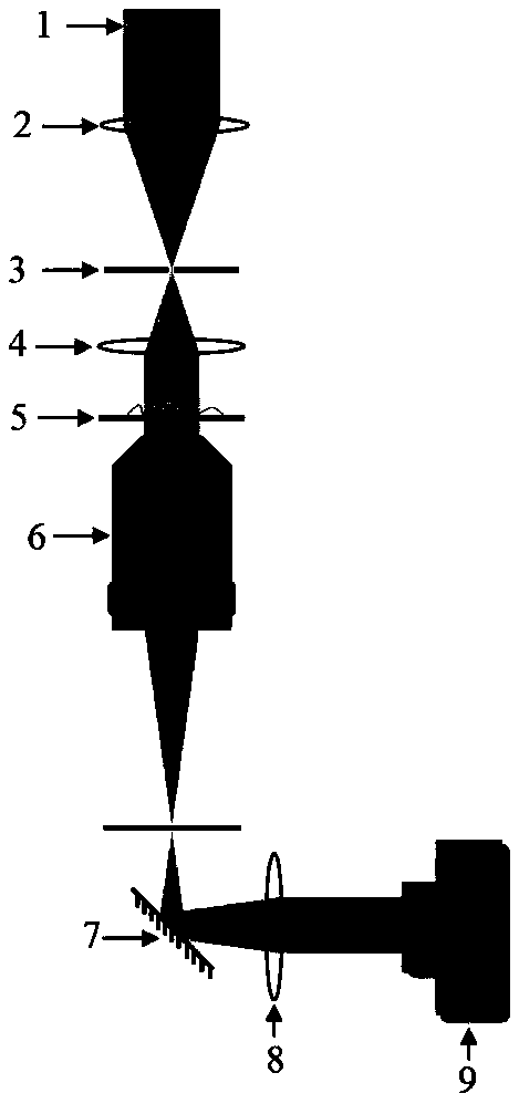
[0031] Embodiment 1: a kind of optical microscope system light path that realizes this method is as image 3 As shown, it includes: a halogen light source 1, a converging lens 2, a diaphragm 3, a converging lens 4, a sample 5, a microscope objective lens 6, a reflector 7, a converging lens 8, and a CCD camera 9. Wherein, the halogen light source becomes partially coherent light after passing through the aperture, and is amplified by the microscope objective lens after passing through the sample, and the light beam carrying object information is collimated by a converging lens after passing through the reflector, and finally utilized The CCD records the intensity map. Among them, the halogen lamp can be replaced with LED as the light source, the magnification of the microscope objective lens can be selected according to actual needs, and the aperture is used to adjust the coherence of the light source.

[0032] The workflow of the described deep learning phase microscopy imagi...


PUM


Abstract

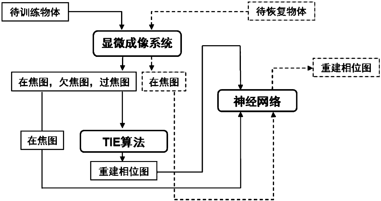
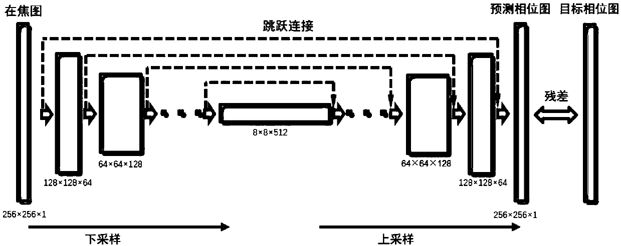
The invention discloses a phase microscopic imaging method based on deep learning, and the method comprises the following steps: employing a microscopic imaging system to collect an under-focus image,an in-focus image, and an over-focus image of a training sample; Obtaining a phase diagram of the training sample by using a phase recovery algorithm based on an intensity transmission equation; Andtaking the in-focus graph of the training sample and the corresponding phase graph as a training set to train the neural network. The training process only needs to be carried out once, then an in-focus image of an unknown sample is collected, and the phase image can be recovered by inputting the in-focus image into the trained network. The method has the advantages that reference light is not needed, a part of coherent light sources can be used, calculation is rapid and fast, limitation of boundary conditions is avoided, phase information of an object can be recovered only through one focus intensity graph, the method can be directly combined with an existing microscopic imaging system at low cost, and phase imaging is achieved while microscopic imaging is conducted.

Description

technical field [0001] The invention relates to the field of optics, in particular to the field of microscopic imaging. Background technique [0002] The microscope is one of the greatest inventions of mankind in the 20th century. Microscopes have brought a whole new world to the human eye. For the first time, people have seen hundreds of "new" tiny animals and plants, as well as the internal structure of various objects from human bodies to plant fibers. However, due to the high frequency of light, the existing image acquisition equipment can only record the intensity information of the light field and cannot directly obtain the phase information. Therefore, the phase information of the light field needs to be recovered by using the intensity information. Traditional phase recovery methods are divided into interferometric methods and non-interferometric methods. The use of interferometry to recover phase information from the interference intensity map requires the light s...

Claims


Application Information

Patent Timeline
IPC IPC(8): G06T5/00G06T5/50G06N3/04
CPCG06T5/50G06T2207/10061G06N3/045G06T5/77
Inventor 邸江磊王凯强李颖豆嘉真戴思清席特立赵建林
Owner NORTHWESTERN POLYTECHNICAL UNIV
Learn More