
Water gas combustion pipeline structure

A combustion tube, water gas technology, applied in combustion methods, combustion equipment, gaseous fuel supply/distribution, etc., can solve the problems of SIC combustion chamber rupture, pressure fluctuation, corrosion, etc., to ensure normal use, improve pass rate, and pressure stability. Effect

Pending Publication Date: 2019-04-26
DLT TECH CO LTD
View PDF0 Cites 0 Cited by
  • Summary
  • Abstract
  • Description
  • Claims
  • Application Information

AI Technical Summary

Problems solved by technology

[0005] (1) Pollution
Although the water gas has passed the treatment of the pressure reducing valve group, there are still some impurities such as residual water vapor, dust (coal powder), tar, etc., and the treatment is not good. First, it will pollute the product after burning; Water can cause SIC combustion chambers to rupture
[0006] (2) Corrosion
[0007] (3) Low calorific value and pressure fluctuation

Method used


Image

  • Water gas combustion pipeline structure
  • Water gas combustion pipeline structure
  • Water gas combustion pipeline structure

Examples


Embodiment Construction

[0036] In order to make the object, technical solution and advantages of the present invention clearer, the present invention will be further described in detail below in conjunction with the accompanying drawings. It is only stated here that the words for directions such as up, down, left, right, front, back, inside, and outside that appear or will appear in the text of the present invention are only based on the accompanying drawings of the present invention, and are not specific to the present invention. limited.

[0037] Such as figure 2 As shown, the total length of the kiln in the present invention is composed of a plurality of modular sections (or single-section kilns), and the length of each modular section is 2.1m / section, and the inner width is determined according to product specifications, process characteristics or customer requirements. The upper and lower parts of each module section (the roller kiln structure can be called roller upper or lower; or the upper ...


PUM


Abstract

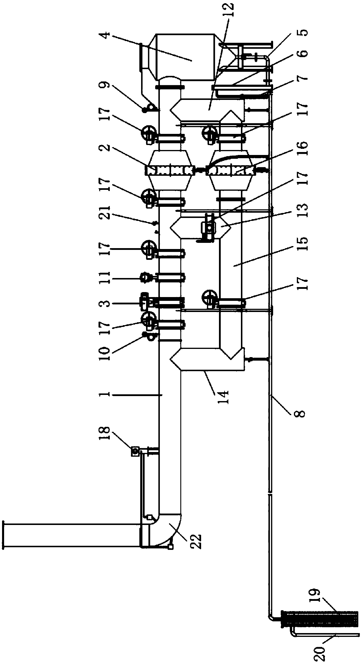
The embodiment of the invention discloses a water gas combustion pipeline structure. The structure comprises a pressure stabilizing and filtering pipe set and a gas distribution pipe set; the pressurestabilizing and filtering pipe set is used for carrying out pressure stabilizing and filtering on water gas supplied by a gas station, the gas distribution pipe set is used for distributing the watergas treated through the pressure stabilizing and filtering pipe set to nozzles of a kiln, through the structure, the pressure stabilizing and filtering pipe set can carry out rapid pressure reducing,pressure stabilizing, water removal and dust removal on the water gas from the gas station and then feeds the water gas to the kiln to be combusted, the gas distribution pipe set can further removalwater in the water gas, finally, the water gas is fed to nozzles in the upper portion and the lower portion of the kiln, and the aim that the nozzles in the upper layer and the lower layer in each combustion pipe set can be subjected to independent temperature control is achieved.

Description

technical field [0001] The invention relates to the field of combustion systems of high-temperature furnaces (including furnaces), in particular to a water gas combustion pipeline structure. Background technique [0002] Water gas (cold gas) is one of the commonly used fuels in ceramic tile kiln firing. It is generated by mixing water vapor and air to form a gasification agent and then flowing through a hot fixed combustion bed. Oxygen and steam contained in the air react with carbon in the fuel to form CO, CO 2 、H 2 , CH compound, N 2 Producer gas with equal composition, water and carbon dioxide will be discharged after combustion, with trace amounts of CO, hydrocarbons, SO 2 , NO X Wait. [0003] Although water gas has certain pollution in the process of gas production and use, such as phenol water, dust (coal powder), etc., as long as ceramic enterprises strengthen environmental protection treatment, they can meet the emission standards. In recent years, government...

Claims


Application Information

Patent Timeline
Patent Type & Authority Applications(China)
IPC IPC(8): F23K5/00C10K1/02C10K1/00
CPCF23K5/005C10K1/002C10K1/024
Inventor 荆海山陶志坚陆志佳程希如郑旭东
Owner DLT TECH CO LTD
Learn More