
Leveling control loop and control method based on hydraulic control self-locking

A technology of control loop and control method, applied in the direction of servo motor components, fluid pressure actuation system components, mechanical equipment, etc.

Active Publication Date: 2020-07-07
THE GENERAL DESIGNING INST OF HUBEI SPACE TECH ACAD
View PDF9 Cites 0 Cited by
  • Summary
  • Abstract
  • Description
  • Claims
  • Application Information

AI Technical Summary

Problems solved by technology

[0002] In actual production, there are many equipment or devices that need to be lifted using multi-point hydraulic lifting devices. In order to ensure that the equipment or devices that need to be lifted remain balanced after lifting, a locking mechanism is also set; and the current leveling with mechanical self-locking function The mechanical self-locking function of the system is mainly through the separate control of the mechanical structure or the design of a special oil cylinder. Traditionally, the locking and unlocking function of the hydraulic cylinder is realized by adding an additional power source control mechanism or designing a special oil cylinder or through additional electrical signal control; while the market There has not been a purely hydraulic circuit to control the unlocking and locking of the mechanical locking device, so this problem needs to be solved urgently

Method used


Image

  • Leveling control loop and control method based on hydraulic control self-locking
  • Leveling control loop and control method based on hydraulic control self-locking

Examples


Embodiment

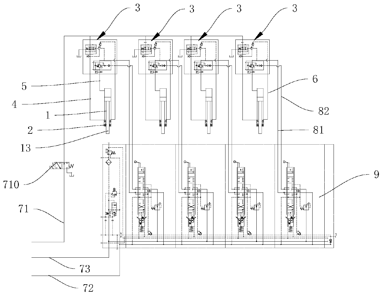
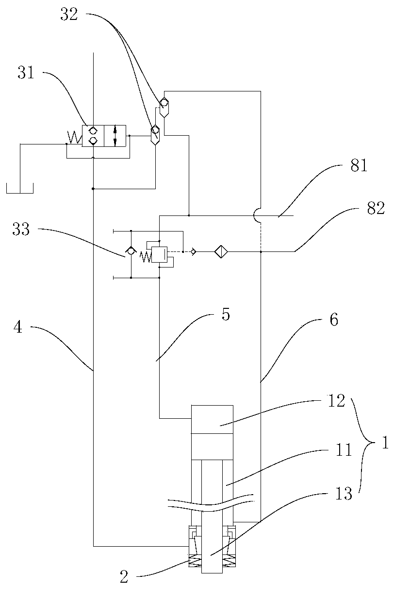
[0044] see Figure 1~2As shown, the embodiment of the present invention provides a leveling control circuit based on hydraulic control self-locking. The leveling control circuit is applied to leveling the hydraulic cylinder 1. The hydraulic cylinder 1 includes a rod chamber 11, a rodless Cavity 12 and hydraulic cylinder rod 13; the leveling control circuit includes a self-locking leveling circuit and a control circuit; the self-locking leveling circuit includes a hydraulic control self-locking valve block 3, a first executive oil circuit 4, a second executive The oil circuit 5, the third executive oil circuit 6 and the mechanical self-locking part 2; the hydraulic control self-locking valve block 3, the first executive oil circuit 4, and the mechanical self-locking part 2 are connected in sequence to limit the hydraulic cylinder rod 13 The movement of the hydraulically controlled self-locking valve block 3, the second executive oil circuit 5, and the rodless cavity 12 are conn...


PUM


Abstract

The invention discloses a leveling control loop and method based on hydraulic control self locking. The leveling control loop is applied to a hydraulic cylinder for leveling; the hydraulic cylinder comprises a rod cavity, a rodless cavity and hydraulic cylinder rods; the leveling control loop comprises a self locking leveling loop and a control loop; the self locking leveling loop comprises a hydraulic control self locking valve block, a first executing oil way, a second executing oil way, a third executing oil way and a mechanical self locking piece; the hydraulic control self locking valve block, the first executing oil way and the mechanical self locking piece are connected in sequence so that motion of the hydraulic cylinder rods can be limited; the hydraulic control self locking valveblock, the second executing oil way and the rodless cavity are connected in sequence so that the hydraulic cylinder rods can be controlled to stretch out; the hydraulic control self locking valve block, the third executing oil way and the rod cavity are connected in sequence so that the hydraulic cylinder rods can be controlled to draw back; and the control loop is connected with the hydraulic control self locking valve block so that the first executing oil way, the second executing oil way and the third executing oil way can be controlled to act on the hydraulic cylinder rods. According to the leveling control loop and method based on hydraulic control self locking, telescopic control over the multiple hydraulic cylinder rods is achieved with hydraulic pressure as driving force, and theleveling purpose is achieved.

Description

technical field [0001] The invention relates to the technical field of hydraulic control, in particular to a leveling control circuit and control method based on hydraulic control and self-locking. Background technique [0002] In actual production, there are many equipment or devices that need to be lifted using multi-point hydraulic lifting devices. In order to ensure that the equipment or devices that need to be lifted remain balanced after lifting, a locking mechanism is also set; and the current leveling with mechanical self-locking function The mechanical self-locking function of the system is mainly through the separate control of the mechanical structure or the design of a special oil cylinder. Traditionally, the locking and unlocking function of the hydraulic cylinder is realized by adding an additional power source control mechanism or designing a special oil cylinder or through additional electrical signal control; while the market There is no pure hydraulic circu...

Claims


Application Information

Patent Timeline
Patent Type & Authority Patents(China)
IPC IPC(8): F15B15/26F15B13/02F15B21/00
CPCF15B13/02F15B15/26F15B21/00
Inventor 洪建军郭邵波熊俊王辉邓刚吴穹雷建红
Owner THE GENERAL DESIGNING INST OF HUBEI SPACE TECH ACAD
Learn More