
Wall screeding equipment for building decoration

A wall and building technology, applied in construction, building structure, cement mixing device, etc., can solve the problems of uneven plastering, device shaking, soiling of artificial clothes, etc., so as to avoid splashing on clothes and avoid precipitation of raw materials. , to avoid the effect of device shaking

Inactive Publication Date: 2022-07-08
赵伟
View PDF0 Cites 0 Cited by
  • Summary
  • Abstract
  • Description
  • Claims
  • Application Information

AI Technical Summary

Problems solved by technology

[0002] Most of the interior and exterior walls in the construction industry are plastered manually. This method is inefficient, slow, and takes up a lot of time and labor. Moreover, the mortar is fluid. When manually plastering, the mortar will be scattered on the ground. In addition, the artificial clothes will be dirty. Most of the existing plastering machines stand upright on the wall to squeeze the mortar, which will cause uneven distribution of the mortar. Because the plastering device is relatively high, when plastering the wall , it is easy to cause the device to shake, resulting in uneven plastering. When the current plastering machine is working, the plastering machine is placed on the side of the wall for plastering, but if the ground is uneven, the plastering device does not have a leveling function , when plastering, it will cause some walls not to be plastered with mortar, so it is urgent to make a wall plastering equipment for building decoration

Method used


Image

  • Wall screeding equipment for building decoration
  • Wall screeding equipment for building decoration
  • Wall screeding equipment for building decoration

Examples


Embodiment Construction

[0042] A specific embodiment of the present invention will be described in detail below with reference to the accompanying drawings, but it should be understood that the protection scope of the present invention is not limited by the specific embodiment.

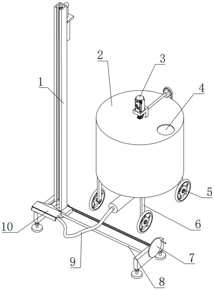
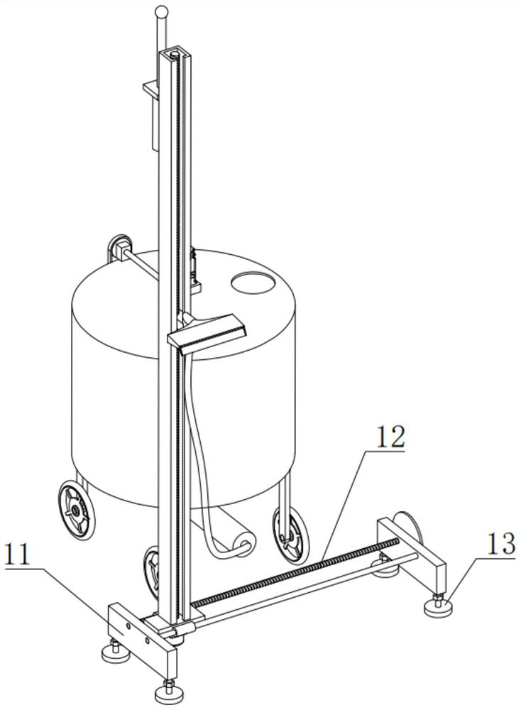
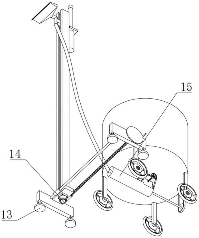
[0043] like Figure 1-Figure 17 As shown, the present invention includes a box body 2, the upper side of the box body 2 is eccentrically provided with a feeding port 4, the lower end of the box body 2 is fixedly connected to the upper side of the box body 27, and the lower side of the box body 27 is fixed with a communication pipe One end of the upper side of the body 15;

[0044] The upper side of the box body 2 is fixedly connected to the lower side of the vertical plate of the L-shaped plate 30, one end of the upper side of the box body 2 is fixedly connected to the lower side of the mounting block 28, and the inner upper side of the box body 2 is fixedly connected to the upper side of the gear ring 36;

[0045] Correspond...


PUM


Abstract

The wall screeding equipment for building decoration comprises a box body and is characterized in that a feeding port is formed in the eccentric position of the upper side of the box body, the lower end of the box body is fixedly communicated with the upper side of a box body, the lower side of the box body is fixedly communicated with one end of the upper side of the box body, and the upper side of the box body is fixedly connected with the lower side of a vertical plate of an L-shaped plate; one end of the upper side of the box body is fixedly connected with the lower side of a mounting block, the upper side of the interior of the box body is fixedly connected with the upper side of a gear ring, corresponding rectangular grooves are formed in the two sides of the box body, and the four corners of the lower side of the box body are fixedly connected with the upper ends of corresponding mounting rods correspondingly. Relates to wall screeding equipment for building decoration. According to the device, mortar can be conveyed into the hose at a constant speed through the spiral blade shaft, the mortar is uniformly conveyed into the smearing head through the hose, the mortar uniformly flows out of the smearing head, the mortar is uniformly smeared on a wall through the smearing head, and splashing of the mortar is reduced.

Description

technical field [0001] The invention relates to the field of wall leveling equipment, in particular to a wall leveling equipment for building decoration. Background technique [0002] When plastering and plastering the inner and outer walls of the construction industry, most of the construction is carried out manually. This method is inefficient, slow, takes up a lot of construction time and labor, and the mortar has fluidity. When manual plastering is performed, the mortar will be scattered on the ground. On the other hand, artificial clothes will be soiled. Most of the existing plastering machines are erected on the wall to squeeze the mortar, which will cause uneven distribution of the mortar. Due to the high plastering device, when plastering the wall , it is easy to cause the device to shake, resulting in uneven plastering. When the current plastering machine is working, the plastering machine is placed on the side of the wall for plastering, but if the ground is uneven...

Claims


Application Information

Patent Timeline
Patent Type & Authority Applications(China)
IPC IPC(8): E04F21/08E04F21/16B28C5/16
CPCE04F21/08E04F21/16B28C5/16Y02P70/10
Inventor 赵伟
Owner 赵伟
Learn More