


Quick Research
Generate reliable direction feasibility study reports for your R&D in just a few steps.

Technical Q&A
Discover and master advanced knowledge NOW. Basics, ideas, possibilities, all at once.

Find Solutions
As an expert in R&D theories, this can generate solutions to your technical problems instantly.

Evaluate Feasibility
Analyze your overall solution with one click, know your potential R&D risks in advance.

Monitor Landscape
Get weekly tech updates, stay abreast of the latest tech innovations and key insights.
Implantable medical detection equipment
A medical testing equipment, implantable medical technology, applied in medical science, pulse rate/heart rate measurement, diagnostic recording/measurement, etc., can solve problems such as battery replacement, avoid secondary damage, and meet implantation requirements.
- Summary
- Abstract
- Description
- Claims
- Application Information
AI Technical Summary
Problems solved by technology
Method used
Image

Examples
Embodiment 1
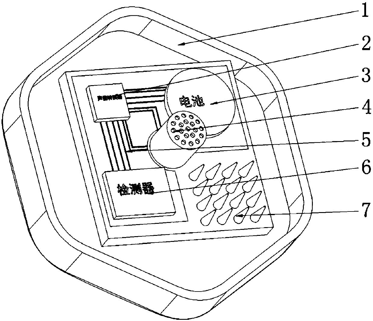
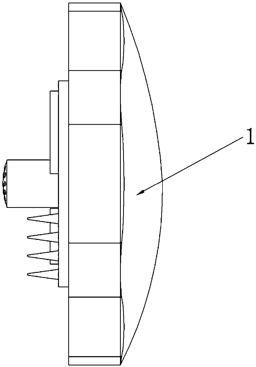
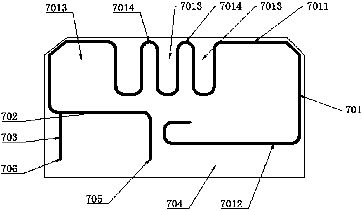
[0018] Embodiment 1 is basically as attached figure 1 and figure 2 Shown: an implantable medical detection device, including a device box 1, a medical unit set in the device box 1, and a communication antenna 7 for allowing the medical unit to communicate with the outside world, and the outer surface of the device box 1 is an arc surface , the device box 1 is made of transparent materials, and the outside of the device box 1 is sprayed with a food-grade anti-corrosion coating; the medical unit includes a detection circuit 5, a detector 6, a storage battery 3 and a miniature Holmes for charging the storage battery 3 The acoustic energy generator 4, the miniature Holmtz acoustic energy generator 4 includes a Holmtz resonator and an acoustic-electric transducer 2, and a plurality of sound wave receiving holes are opened on the outer surface of the Holmtz resonator, and the Hall There are multiple sound wave output holes on the inner surface of the Mutz resonator, and each sound...
Embodiment 2
[0021] The difference between Embodiment 2 and Embodiment 1 is that the miniature Holmtz acoustic energy generator 4 is replaced by an acoustic crystal resonator acoustic energy power generation system, and the acoustic crystal resonator acoustic energy power generation system is converted by acoustic crystals and piezoelectric materials. The power generator is connected to the speaker as the sound source, the acoustic crystal is fixed on a PMMA plate to form a resonant cavity, and the piezoelectric transducer is placed in the acoustic crystal cavity for energy conversion.
Embodiment 3
[0022] The difference between embodiment 3 and embodiment 1 is only that the miniature Holmes acoustic energy generator 4 is replaced by a DC nano-acoustic energy generator. Including nanowires, electric saw-toothed electrodes and nanogenerators, a layer of zinc oxide film is on the bottom of the nanowires as an electrode of the nanogenerator, and the other electrode is placed on the top of the nanoscale and fixed with a soft polymer. There is still a gap between the top electrode and the nanowire, so that they can carry out relative vibration or deformation of the degree of movement. When the external sound wave is transmitted to the nanogenerator, it will cause the top electrode to vibrate up and down and the nanowire to swing left and right. Or resonance, thereby converting sound energy into electrical energy.
[0023] It should be noted that since the implanted medical testing equipment is small and uses relatively little electricity, the acoustic power generation system o...
PUM
 Abstract
Description
Claims
Application Information
 - R&D Engineer
- R&D Manager
- IP Professional
- Industry Leading Data Capabilities
- Powerful AI technology
- Patent DNA Extraction
Browse by: Latest US Patents, China's latest patents, Technical Efficacy Thesaurus, Application Domain, Technology Topic, Popular Technical Reports.
© 2024 PatSnap. All rights reserved.Legal|Privacy policy|Modern Slavery Act Transparency Statement|Sitemap|About US| Contact US: help@patsnap.com