Flexibly contractive water quality sampler
A water quality sampler and flexible technology, applied in the direction of sampling devices, etc., can solve the problems of difficulty in collection, inability to automatically adjust the volume of the sampler, and the water quality sampler cannot adjust the position of water quality sampling, etc., achieving convenient control steps and convenient adjustment and control. Fast, sample-flexible effects
- Summary
- Abstract
- Description
- Claims
- Application Information
AI Technical Summary
Problems solved by technology
Method used
Image
Examples
Embodiment 1
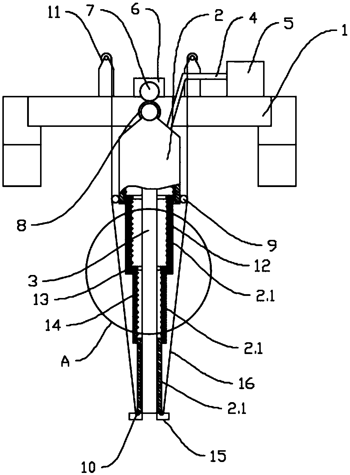
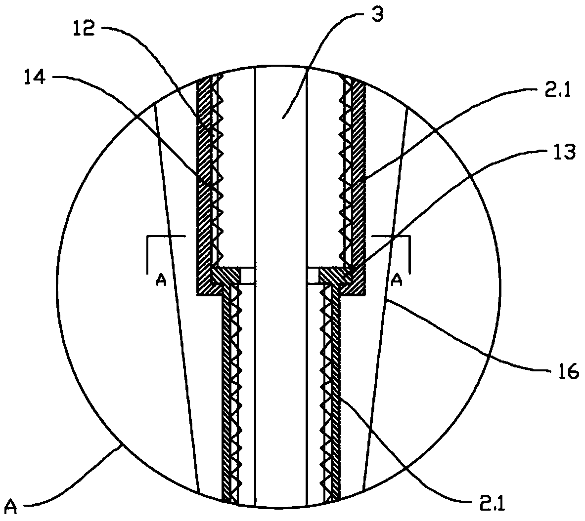
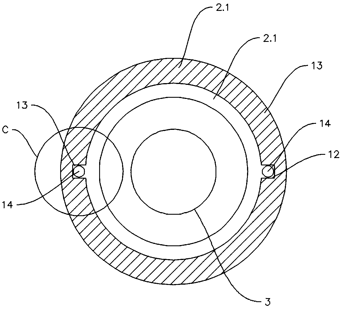
[0044] This embodiment provides a flexible and shrinkable water quality sampler, such as Figure 8 As shown, it includes a mounting bracket 1, a lifting unit installed on the mounting bracket 1, and a sleeve structure 2 that cooperates with the pulling unit to realize the contraction function. The upper end of the sleeve structure 2 is hinged with the mounting bracket 1, and the sleeve structure 2 includes A plurality of sleeve units 2.1 are sequentially socketed, and a sliding fit structure is provided between adjacent sleeve units 2.1 to realize an axial sliding fit between the two. The sleeve unit 2.1 located at the head of the sleeve structure 2 and the The casing unit 2.1 at the tail of the tube structure 2 is provided with a pulling connection part, and the area between the pulling connection parts is a contraction zone, and the length of the contraction zone can be changed by operating the pulling unit; the casing structure 2 There is a telescopic tube 3 inside, the wat...
Embodiment 2
[0050] This embodiment is optimized and defined on the basis of the above-mentioned embodiment 1.
[0051] Such as Figure 8 As shown, it also includes an angle adjustment mechanism installed on the mounting bracket 1 and used to adjust the angle of the casing structure 2; the casing unit 2.1 located at the head of the casing structure 2 is provided with a hinge, and the hinge and the mounting bracket 1 hinged, the angle adjustment mechanism includes a motor 6, a gear one 7 located at the driving end of the motor 6, and a gear two 8 fixedly connected to the hinge, the gear one 7 meshes with the gear two 8.
[0052] The motor 6 directly drives the gear one 7 to rotate, and the gear two 8 is driven to rotate while the gear one 7 rotates, thereby realizing the swing of the casing structure 2 driven by the gear two 8, and the swing range of the sleeve structure 2 is realized by controlling the rotation range of the motor 6 adjust.
[0053] The design of the angle adjustment stru...
Embodiment 3
[0055] This embodiment is optimized and defined on the basis of the above-mentioned embodiment 2.
[0056] Such as Figure 8 As shown, the lifting connection part is the lifting ring 1 symmetrically arranged on the casing unit 2.1 located at the head of the casing structure 2 and the lifting ring 2 symmetrically arranged on the casing unit 2.1 located at the tail of the casing structure 2 10. The pulling unit includes a wire winding machine 11 symmetrically installed on the installation bracket 1 , and the pull rope 16 on the wire winding machine 11 passes through the corresponding pulling ring one 9 and is fixedly connected with the corresponding pulling ring two 10 .
[0057] The stay rope 16 on the wire winding machine 11 passes through the corresponding lifting ring one 9 and is fixedly connected with the corresponding lifting ring two 10. When the wire winding machine 11 pulls the stay rope 16, the stay rope 16 is directly lifted The cannula unit farthest from the hinge ...
PUM
 Abstract
Description
Claims
Application Information
 - R&D
- Intellectual Property
- Life Sciences
- Materials
- Tech Scout
- Unparalleled Data Quality
- Higher Quality Content
- 60% Fewer Hallucinations
Browse by: Latest US Patents, China's latest patents, Technical Efficacy Thesaurus, Application Domain, Technology Topic, Popular Technical Reports.
© 2025 PatSnap. All rights reserved.Legal|Privacy policy|Modern Slavery Act Transparency Statement|Sitemap|About US| Contact US: help@patsnap.com


