
Construction method for bearing overlapped heat-insulating floor slab

A construction method and thermal insulation board technology, applied in the direction of floor slabs, building structures, building components, etc., can solve the problems of complex formwork support, formwork removal, lack of thermal insulation effect, mold waste, etc., to achieve improved thermal insulation effect, good Waterproof, effect of reducing workload

Inactive Publication Date: 2019-04-23
绿建科技集团新型建材高技术有限公司
View PDF0 Cites 2 Cited by
  • Summary
  • Abstract
  • Description
  • Claims
  • Application Information

AI Technical Summary

Problems solved by technology

[0003] The technical scheme of the laminated floor slab in the prior art is to have prefabricated ribs on the prefabricated cement slab, fill the space between the prefabricated ribs with insulation material, then place the prefabricated cement slab on the beam or wall, and set steel bars on it, and then Concrete is poured on site to form the floor slab in the prefabricated building. The process of formwork support and demolition of this technical solution is relatively complicated, resulting in waste of molds, and does not have the effect of heat preservation

Method used


Image

  • Construction method for bearing overlapped heat-insulating floor slab
  • Construction method for bearing overlapped heat-insulating floor slab
  • Construction method for bearing overlapped heat-insulating floor slab

Examples


preparation example Construction

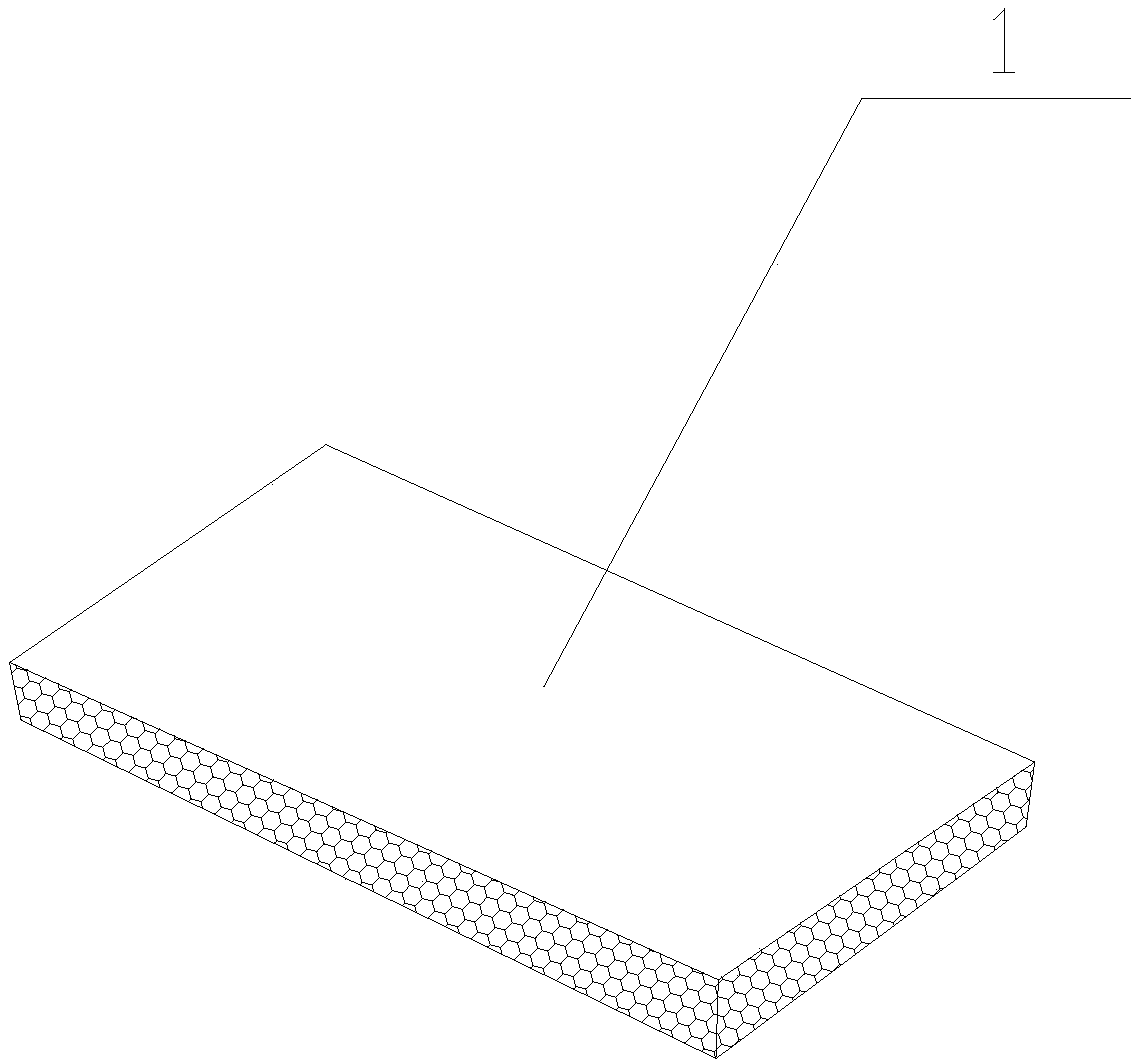
[0032] (1) Preparation of insulation board 1: The insulation board 1 includes at least an insulation layer 11, which is made of cement and aggregates. The aggregates include agricultural and forestry wastes and / or lightweight aggregates. Aggregates are mixed to make thermal insulation mortar, which is poured into a mold to form thermal insulation board 1;

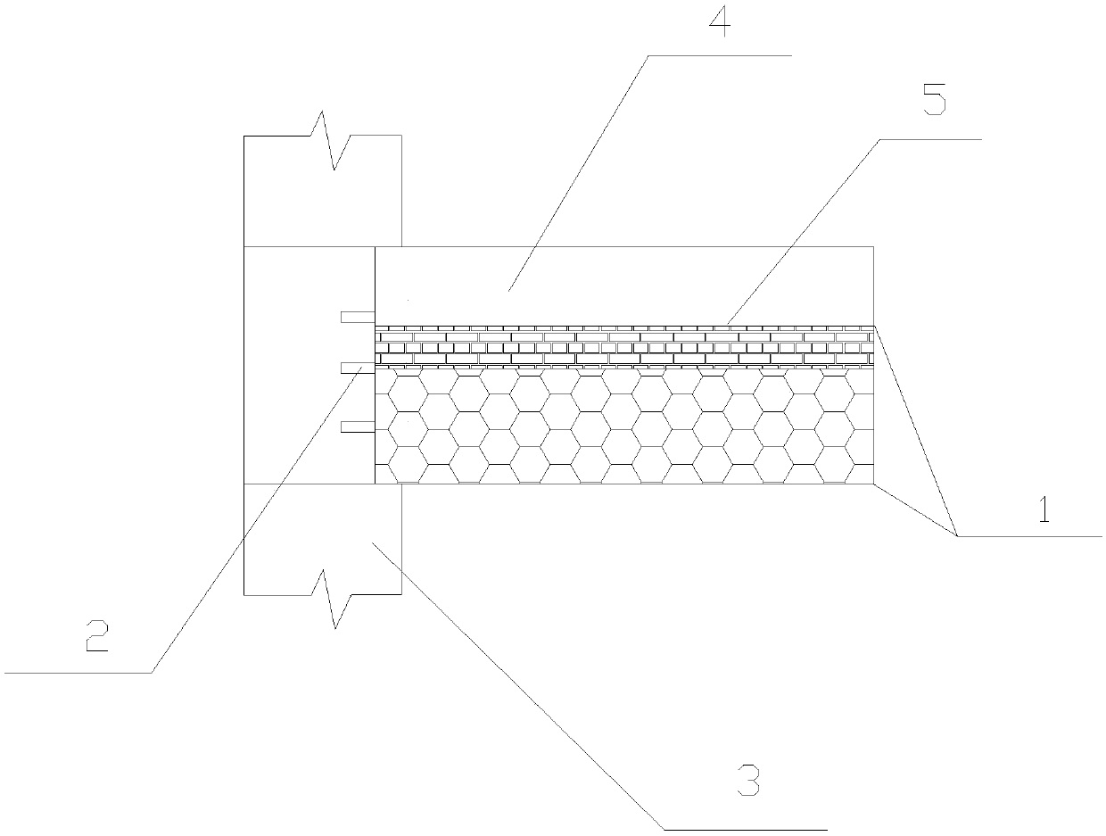
[0033] (2) Hoisting of insulation board 1: hoisting and placing the insulation board 1 formed in step (1) on the beam or wall 3, and then laying steel bars 2 on the insulation board 1;

[0034] (3) Cast-in-situ of the laminated layer: use the thermal insulation board 1 directly as a template to pour the concrete to construct the cast-in-place load-bearing floor 4, and the end of the thermal insulation board 1 is fixed integrally with the beam or wall 3 through the cast-in-place concrete. The cement slurry of the load-bearing floor 4 penetrates into the thermal insulation board 1, solidifies with the aggregates in the thermal ins...

specific Embodiment approach 1

[0045] Such as figure 1 , figure 2 As shown, an overlapped thermal insulation board 1 is mixed with cement, crop straws, and ceramsite to form a thermal insulation board 1. The thermal insulation board 1 has steel bars 2 placed in it to increase the strength of the thermal insulation board 1. The thermal insulation board 1 is placed on the beam or wall 3, and then steel bars 2 are arranged on the thermal insulation board 1, and then concrete is cast in-situ to form the cast-in-place load-bearing floor 4, and the cement slurry of the cast-in-place load-bearing floor 4 penetrates Into the thermal insulation board 1, solidify with the lightweight aggregate in the thermal insulation board 1 to form a thermal insulation solidification bonding layer 5 in the thermal insulation board 1. The thermal insulation solidification bonding layer 5 connects the thermal insulation board 11 with the The cast-in-place load-bearing floor 44 is solidified into one body to form a non-interface beari...

specific Embodiment approach 2

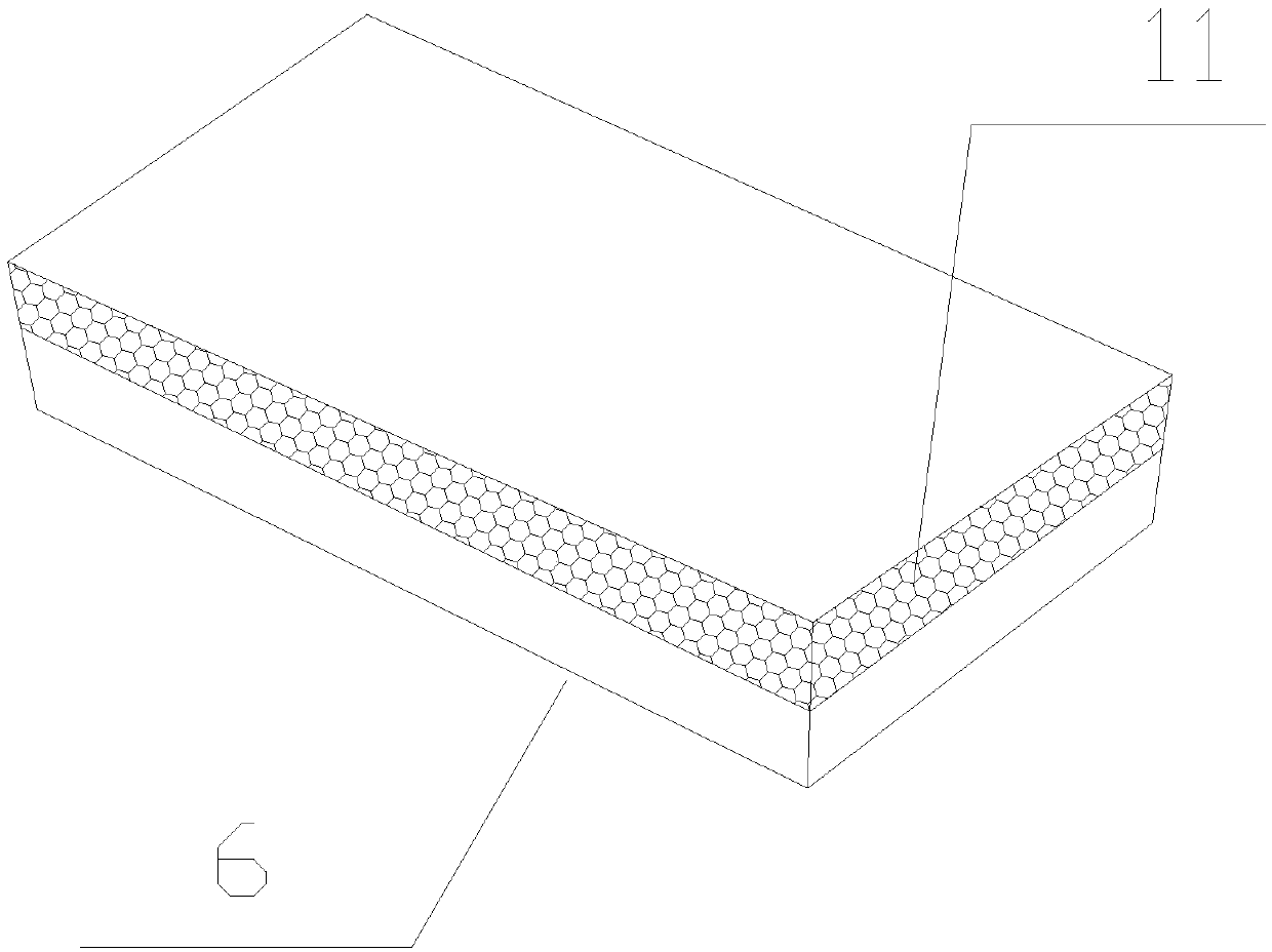
[0046] Such as image 3 , Figure 4 As shown, a kind of superimposed thermal insulation floor slab is made of concrete and steel bar 2 to make a load-bearing board 6, then mixed with cement, straw, and ceramsite, and poured on the load-bearing board 6 to form an insulation layer 11 and a load-bearing board 6. It is combined with the insulation layer 11 to form the load-bearing insulation board 1. Place the load-bearing insulation board 1 on the beam or wall 3, and then set the steel bars 2 on the load-bearing insulation board 1, and then cast concrete to make the cast-in-place The load-bearing floor 4, the cement slurry of the cast-in-place load-bearing floor 4 penetrates into the insulation layer 11 in the load-bearing insulation board 1, solidifies with the lightweight aggregate in the insulation layer 11, and forms in the insulation layer 11 The thermal insulation solidification bonding layer 5, the thermal insulation solidification bonding layer 55 solidifies the thermal ins...


PUM


Abstract

The invention relates to a construction method for a bearing overlapped heat-insulating floor slab. The construction method comprises the following steps: (1) preparation of a heat-insulating board: preparing heat-insulating mortar by mixing cement and aggregates, and then pouring in a mold, thereby forming the heat-insulating board, wherein the heat-insulating board at least comprises a heat-insulating layer; the heat-insulating layer is prepared from cement and aggregates; the aggregates include forestry and agricultural residues and / or lightweight aggregates; (2) hoisting of the heat-insulating board; (3) cast-in-place of overlapped layer: directly taking the heat-insulating board as a template, pouring concrete, permeating cement slurry into the heat-insulating board, solidifying withthe aggregates in the heat-insulating board, forming a heat-insulating solidified bonding layer in the heat-insulating layer of the heat-insulating board, and integrally connecting the heat-insulatingboard with a cast-in-place bearing floor by the heat-insulating solidified bonding layer, thereby forming an interface-free bearing overlapped heat-insulating floor slab. The heat-insulating floor slab has high structural integrity, is free from interface, is high in stretching bonding strength and is different from the traditional overlapped floor slab structure. The heat-insulating board is directly used as the template, so that the heat-insulating effect of the floor slab is promoted and the construction efficiency is increased.

Description

Technical field [0001] The invention belongs to the technical field of industrial and civil self-insulation buildings, and specifically relates to a construction method for supporting and overlapping thermal insulation floor slabs. Background technique [0002] With the development of economy and society, saving energy and protecting the environment have become the consensus of mankind, and reducing energy consumption has become the goal of human joint efforts. In order to save energy more effectively, energy-saving buildings have become an important issue. Improving the thermal insulation performance of buildings can have a significant effect on the energy consumption caused by air conditioning. Therefore, buildings use high-performance thermal insulation materials The demand has also increased. [0003] The technical scheme of the laminated floor in the prior art is to have prefabricated ribs on the prefabricated cement slab, fill the prefabricated ribs with thermal insulation m...

Claims


Application Information

Patent Timeline
IPC IPC(8): E04B5/17E04B5/00
CPCE04B5/17E04B5/00
Inventor 谢向荣谢怀宇易自力沈鸣周文新喻鹏谢向阳
Owner 绿建科技集团新型建材高技术有限公司
Learn More