
Optical filter and preparation method thereof, fingerprint recognition module and electronic device

A technology of filter and long-wave-pass film system, applied in filter, character and pattern recognition, optics, etc., can solve the problem of unable to meet the requirements of fingerprint sensor module use

Pending Publication Date: 2019-04-19
ZHEJIANG CRYSTAL OPTECH
View PDF5 Cites 19 Cited by
  • Summary
  • Abstract
  • Description
  • Claims
  • Application Information

AI Technical Summary

Problems solved by technology

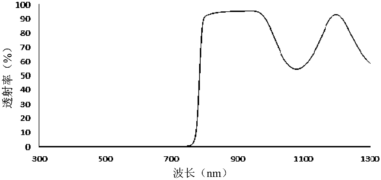
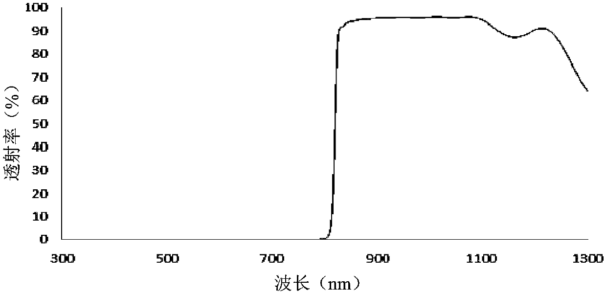
[0010] However, there is no near-infrared filter with high transmittance in the 830-950nm spectral band and a wide cut-off in the 300-750nm spectral band in the prior art, which cannot meet the requirements for use in fingerprint sensor modules.

Method used


Image

  • Optical filter and preparation method thereof, fingerprint recognition module and electronic device
  • Optical filter and preparation method thereof, fingerprint recognition module and electronic device
  • Optical filter and preparation method thereof, fingerprint recognition module and electronic device

Examples


Embodiment 1

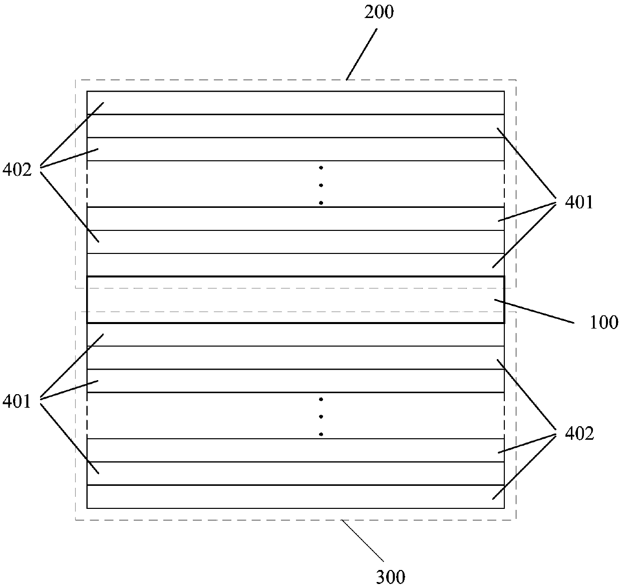
[0043] An embodiment of the present invention provides an optical filter, the optical filter is a near-infrared optical filter through 830-950nm. figure 1 A structural schematic diagram of an optical filter provided for an embodiment of the present invention, such as figure 1 As shown, the filter includes a transparent substrate 100 and a first long-wave pass film system 200 and a second long-wave pass film system 300 respectively arranged on both sides of the transparent substrate 100; the first long-wave pass film system 200 and the second long-wave pass film system All systems 300 include alternately stacked high-refractive-index film layers 401 and low-refractive-index film layers 402; the film system structure of the first long-wave pass film system 200 includes (0.5HL0.5H)^10, and the The central wavelength of the transition zone is 700-900nm; the film structure of the second long-wave pass film system 300 includes (0.5HL0.5H)^14, and the transition zone center wavelengt...

Embodiment 2

[0068] The embodiment of the present invention also provides a method for preparing an optical filter, which can be completed in a vacuum sputtering coating machine, and the optical filter as in the first embodiment above can be prepared by this method. The method includes:

[0069] forming a first long-wave pass film system and a second long-wave pass film system respectively on both sides of the transparent substrate to obtain an optical filter;

[0070] Wherein, the first long-wave pass film system and the second long-wave pass film system both include alternately stacked high-refractive index film layers and low-refractive index film layers; the film structure of the first long-wave pass film system includes (0.5HL0.5H)^ 10. The central wavelength of the transition zone of the first long-wave pass film system is 700-900nm; the film structure of the second long-wave pass film system includes (0.5HL0.5H)^14, and the transition zone center wavelength of the second long-wave p...

Embodiment 3

[0090] The embodiment of the present invention also provides a fingerprint identification module, which includes the optical filter of the first embodiment above.


PUM


Abstract

The invention provides an optical filter and a preparation method thereof, a fingerprint recognition module and an electronic device and relates to the technical field of optical film. The optical filter comprises a transparent substrate and a first long wave pass film system and a second long wave pass film system arranged on the two sides of the transparent substrate; the film system structure of the first long wave pass film system includes (0.5HL0.5H)^10, and center wavelength of a transition tape is 700-900 nm; the film system structure of the second long wave pass film system includes (0.5HL0.5H)^14, and center wavelength of a transition tape is 780-900 nm, wherein H refers to a high-refractivity film layer, and L refers to a low-refractivity film layer. The optical filter has high transmittance at 830-950 nm band and wide stop-band at 300-750 nm spectrum; passband and stop-band features of the optical filter with the spectrum are greatly modified, so that the service requirementof a fingerprint sensor module can be met.

Description

technical field [0001] The invention relates to the technical field of optical thin films, in particular to an optical filter and a preparation method thereof, a fingerprint identification module and electronic equipment. Background technique [0002] At present, in the fingerprint sensor module of electronic products such as mobile phones, there is an urgent need for a filter that meets the following requirements: [0003] (1) High transmittance in the 830-950nm spectrum; [0004] (2) In the 300-750nm spectrum band, it has the function of suppressing optical signals to reduce the influence of signal noise; [0005] (3) It can still be used after being placed for a long time in an environment with low temperature (-40°C), high temperature (+85°C), high humidity (90%) and changes in cold and heat cycles; [0006] (4) The thickness of the base is small (<0.3mm) to meet the miniaturization requirements of the overall structure of the module; [0007] (5) Under the repeate...

Claims


Application Information

Patent Timeline
IPC IPC(8): G02B5/20G06K9/00C23C14/35C23C14/10C23C14/06
CPCG02B5/201G02B5/207C23C14/06C23C14/10C23C14/35G06V40/1324
Inventor 陆张武王迎徐征驰李恭剑
Owner ZHEJIANG CRYSTAL OPTECH
Learn More