A processing method of a bearing seat shell with a small orifice and a large cavity
A processing method and bearing seat technology, which are applied to the rigid brackets of bearing components, shafts and bearings, bearing components, etc., can solve the problems of unqualified product quality and many processing steps, and achieve the unified benchmark, ensure consistency, and improve Effects of Geometric and Dimensional Tolerance Requirements
- Summary
- Abstract
- Description
- Claims
- Application Information
AI Technical Summary
Problems solved by technology
Method used
Image

Examples
specific Embodiment approach 1
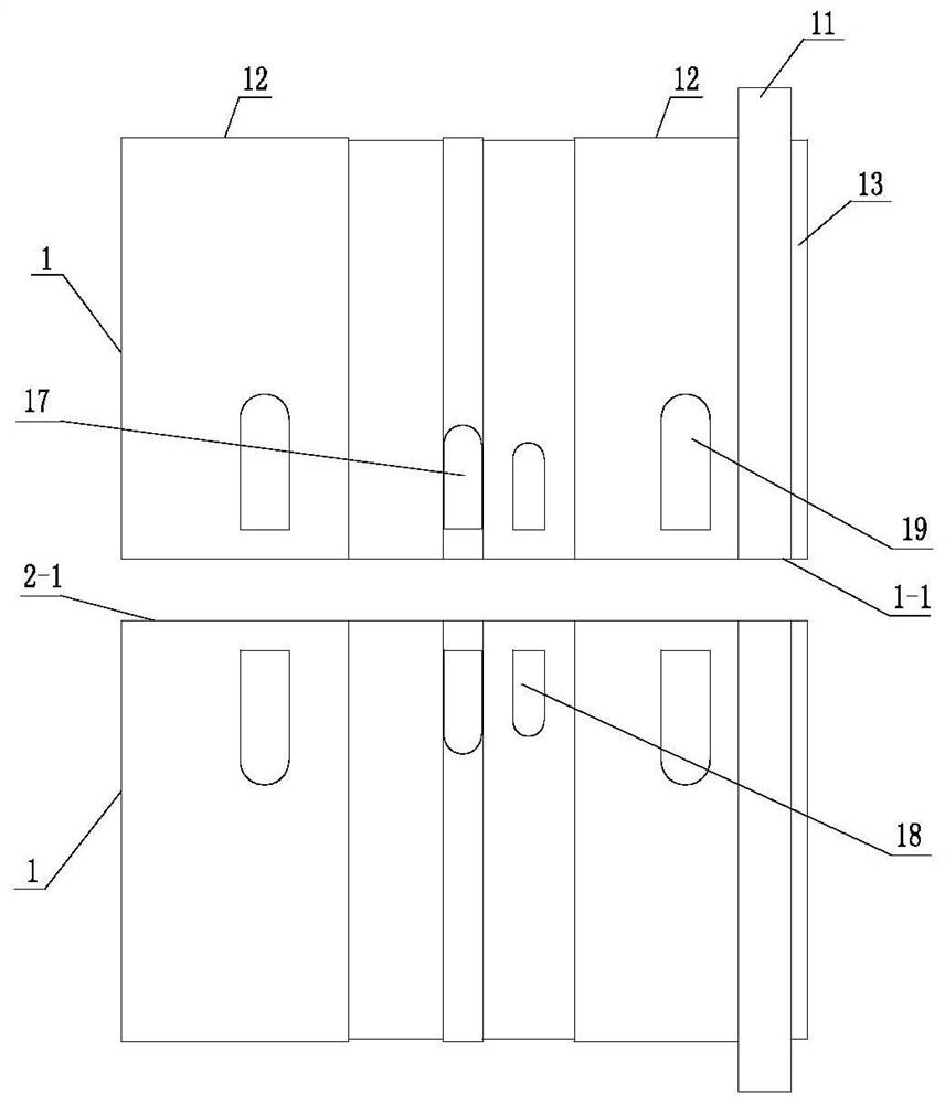
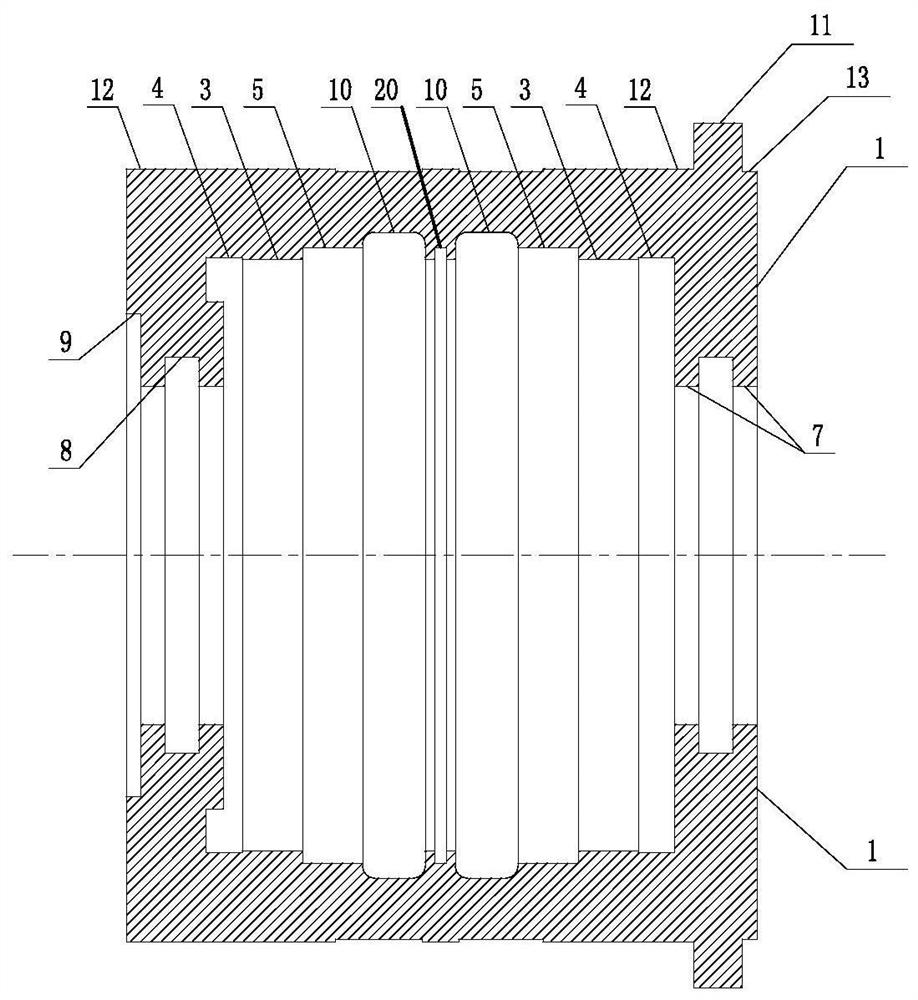
[0045] Specific implementation mode one: as figure 1 and figure 2 As shown, the bearing seat shell described in this embodiment is composed of two identical semi-annular bearing seat shells 1;
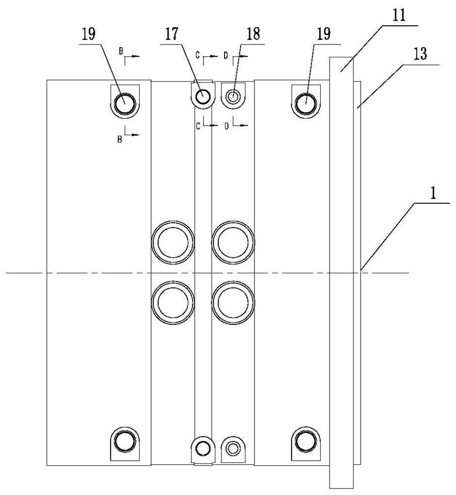
[0046] A set of holes are respectively set at the front and rear ends of each semi-annular bearing housing 1, and the mid-section planes of the two semi-annular bearing housings 1 are aligned and fixedly connected by bolts;
[0047]The outer surface of the bearing housing is provided with a ring of protrusions, forming an annular protrusion 11, which is close to the right end of the bearing housing, and the axis of the annular protrusion 11 coincides with the axis of the bearing housing; The diameter of the first outer circle 12 of the bearing housing on the left side of the annular protrusion 11 is greater than the diameter of the second outer circle 13 of the bearing housing on the right side of the annular protrusion 11;
[0048] The diameter of the cylinder mouth at the left and...
specific Embodiment approach 2
[0069] Specific implementation mode two: as Figure 11 and 12 As shown, the eccentric imitation tapered tool bar 14 in the fourth step of this embodiment includes a first connecting rod 14-1, a first tool bar seat 14-2 and a first tool seat 14-3; The radial cross section of a connecting rod 14-1 is a pseudo-tapered shape;
[0070] The top of the first connecting rod 14-1 is fixedly connected with the bottom end of the first tool holder 14-3, and the bottom end of the first connecting rod 14-1 is fixedly connected with an end of the first tool holder 14-2; the first connection The side ends of the rod 14-1, the first cutter holder 14-3 and the first cutter holder 14-2 are flush, and the axial centerline of the first connecting rod 14-1 is aligned with the axis of the first cutter holder 14-2. Compared with the axis of the first tool seat 14-3, it is closer to the said side end flush;
[0071] The first tool seat 14-3 is provided with a first clamping groove 14-3-1, and two b...
specific Embodiment approach 3
[0074] Specific implementation mode three: as Figures 8 to 10 As shown, the eccentrically enlarged long-head cutter bar 15 in step four described in this embodiment includes a second connecting rod 15-1, a second cutter bar seat 15-2 and a second tool bar seat 15-3;
[0075] The top of the second connecting rod 15-1 is fixedly connected with the bottom end of the second tool seat 15-3, and the bottom end of the second connecting rod 15-1 is fixedly connected with an end of the second knife bar seat 15-2; the second connection The side ends of the bar 15-1, the second tool bar seat 15-2 and the second tool bar seat 15-3 are flush, and the axis of the second connecting rod 15-1 is aligned with the axis of the second tool bar seat 15-2 and the second tool bar seat 15-2. The axis of the tool seat 15-3 is relatively close to the side end flush;
[0076] The second tool seat 15-3 is provided with a second clamping groove 15-3-1, and two bolt holes with internal threads are opened ...
PUM
| Property | Measurement | Unit |
|---|---|---|
| width | aaaaa | aaaaa |
Abstract
Description
Claims
Application Information
 - R&D
- Intellectual Property
- Life Sciences
- Materials
- Tech Scout
- Unparalleled Data Quality
- Higher Quality Content
- 60% Fewer Hallucinations
Browse by: Latest US Patents, China's latest patents, Technical Efficacy Thesaurus, Application Domain, Technology Topic, Popular Technical Reports.
© 2025 PatSnap. All rights reserved.Legal|Privacy policy|Modern Slavery Act Transparency Statement|Sitemap|About US| Contact US: help@patsnap.com