Water optimization system and method for wet flue gas desulfurization device with high-efficienty dust removal in thermal power plant

A wet flue gas desulfurization and thermal power plant technology, applied in chemical instruments and methods, separation methods, electrostatic effect separation, etc., can solve the problems of high quality and low use of water, high renovation costs, and inability to make full use of reuse water in power plants. , to achieve the effect of improving water reuse rate and obvious economic benefits

Pending Publication Date: 2019-04-19
HUANENG POWER INTERNATIONAL +1
View PDF0 Cites 0 Cited by
  • Summary
  • Abstract
  • Description
  • Claims
  • Application Information

AI Technical Summary

Problems solved by technology

However, in addition to newly-built units, most power plants face problems such as small renovation space and high renovation costs when adding wet electrostatic precipitators, which seriously restricts the smoke concentration at the chimney outlet of the power plant to meet more stringent environmental protection requirements
[0003] In addition, according to the survey, it is known that the wet desulfurization device (FGD) with high-efficiency dust removal is the last link of the flue gas collaborative treatment technology route. In order to ensure that the smoke concentration at the chimney outlet reaches the standard, most power plants use the industrial water of the power plant as flushing water for the demister. As a result, the desulfurization system of the power plant cannot make full use of the reusable water of the power plant, which greatly reduces the reuse rate of water resources in the power plant, and there is a certain phenomenon of high quality and low use of water

Method used


Image

  • Water optimization system and method for wet flue gas desulfurization device with high-efficienty dust removal in thermal power plant

Examples


Embodiment Construction

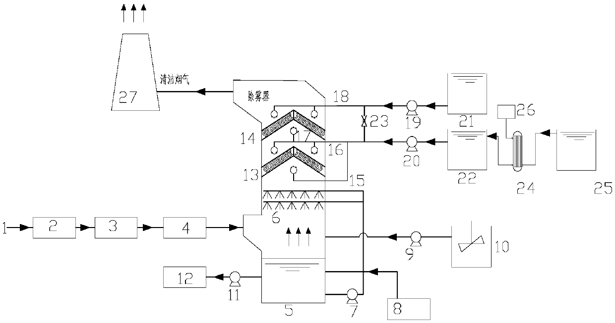
[0025] The present invention is described in further detail below in conjunction with accompanying drawing:

[0026] refer to figure 1 , the water optimization system for the wet flue gas desulfurization device of the thermal power plant with high efficiency dust removal according to the present invention includes a boiler outlet flue gas pipeline 1, a desulfurization absorption tower 5, a reuse water system, a desulfurization industrial water system, an oxidation fan 8 and a chimney 27 The flue gas pipe 1 at the boiler outlet is connected with the flue gas inlet of the desulfurization absorption tower 5, and the desulfurization absorption tower 5 is provided with a spray layer 6, a first layer of flushing water pipe 15, and a first layer of roof type demisting in sequence from bottom to top. device 13, the second layer of flushing water pipe 16, the third layer of flushing water pipe 17, the second layer of ridge type demister 14 and the fourth layer of flushing water pipe 18...


PUM


Abstract

The invention discloses a water optimization system and method for a wet flue gas desulfurization device with high-efficiency dust removal in a thermal power plant, wherein a flue gas pipeline at theoutlet of a boiler is communicated with a flue gas inlet of a desulfurization absorption tower, a spray layer, a first layer of a flushing water pipe, a first layer of a ridge type demister, a secondlayer of the flushing water pipe, a third layer of the flushing water pipe, a second layer of the ridge type demister and a fourth layer of the flushing water pipe are sequentially arranged in the desulfurization absorption tower from bottom to top; the outlet of an oxidation fan and the inlet of the spray layer are both communicated with a slurry pool at the bottom of the desulfurization absorption tower, and a chimney is communicated with a flue gas outlet at the top of the desulfurization absorption tower. The system and method can meet the environmental protection requirement that the concentration value of smoke dust at the outlet of the chimney is lower than 5mg / Nm3, and the cost is lower.

Description

technical field [0001] The invention belongs to the field of energy saving and environmental protection, and relates to a water optimization system and method for a wet flue gas desulfurization device for efficient dust removal in a thermal power plant. Background technique [0002] my country's primary energy structure is dominated by coal, but the total amount of pollutant emissions in coal-fired flue gas remains high, which poses a huge threat to my country's atmospheric environmental problems and has seriously restricted sustainable economic development. Therefore, the state attaches great importance to the pollution control of the atmospheric environment, and stipulates the emission standards for flue gas from power plants. 2 , NOx, and mercury emission concentrations are strictly limited. For this reason, some coal-fired power plants in my country also adopt more economical and stable flue gas collaborative treatment technology to meet environmental protection require...

Claims


Application Information

Patent Timeline
IPC IPC(8): B01D53/50B01D53/56B01D53/64B01D53/68B01D53/73B01D53/80B01D53/81B01D53/86B03C3/00
CPCB01D53/502B01D53/56B01D53/64B01D53/68B01D53/73B01D53/80B01D53/81B01D53/8665B03C3/00B01D2257/2047B01D2257/2045B01D2257/602B01D2258/0283B01D2251/404B01D2251/606
Inventor 卢剑申建汛王正江许臻王璟杨宝红
Owner HUANENG POWER INTERNATIONAL
Why Eureka
Try Eureka