
Essential oil reflux-type atomizer

An atomizer and essential oil technology, applied in the field of atomizers, can solve the problems of essential oil waste and poor atomization performance of essential oils, and achieve the effect of reducing essential oil waste and improving atomization performance

Active Publication Date: 2019-04-16
PUZHEN LIFE CO LTD
View PDF10 Cites 4 Cited by
  • Summary
  • Abstract
  • Description
  • Claims
  • Application Information

AI Technical Summary

Problems solved by technology

[0003] The purpose of the present invention is to provide an essential oil return atomizer to solve the problems in the prior art that the atomization performance of essential oil is poor and a large amount of essential oil will be wasted

Method used


Image

  • Essential oil reflux-type atomizer
  • Essential oil reflux-type atomizer
  • Essential oil reflux-type atomizer

Examples


Embodiment 1

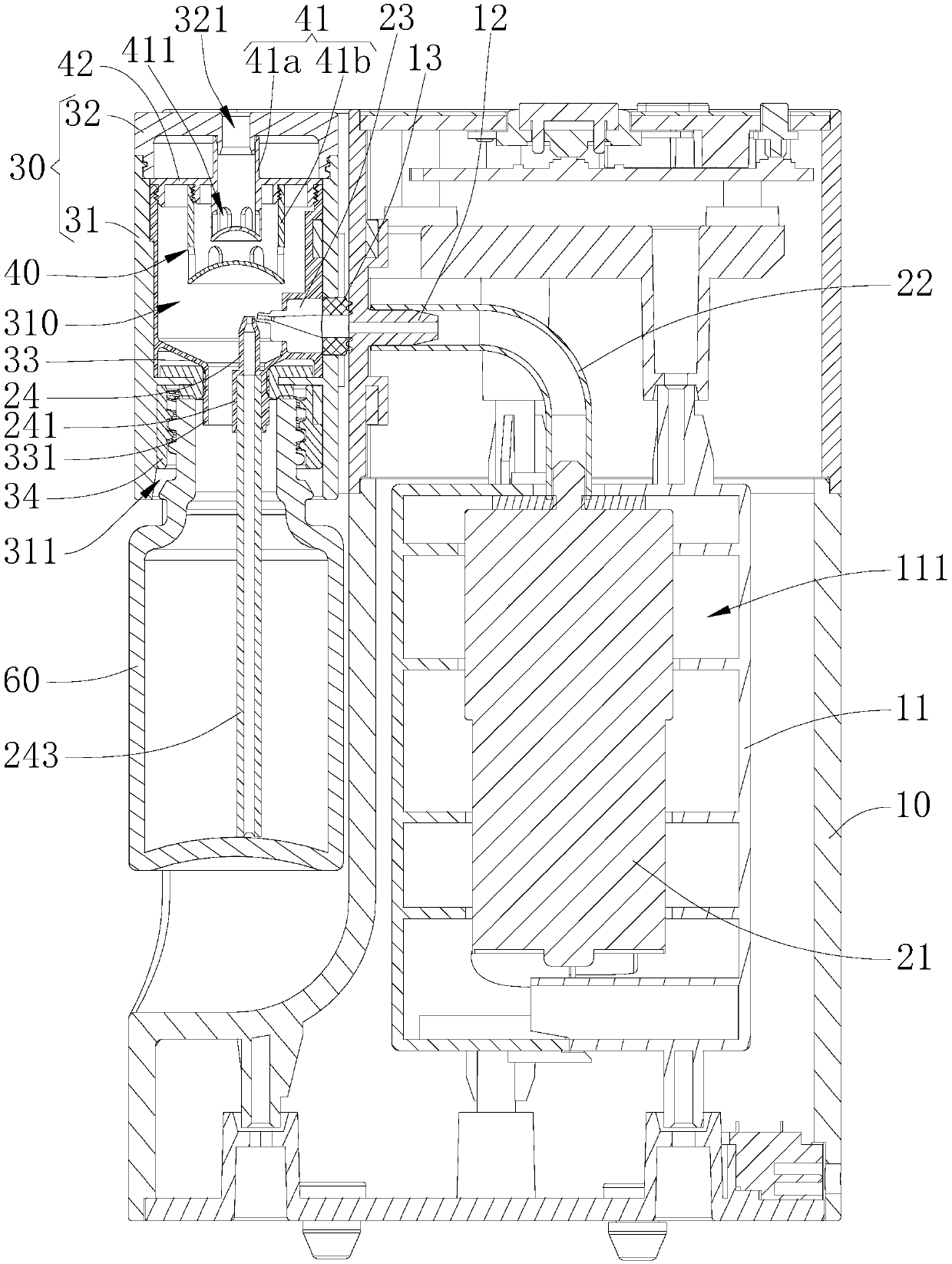
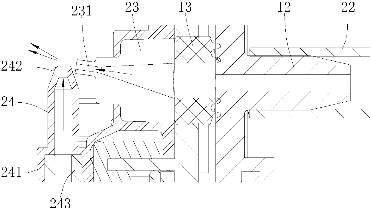
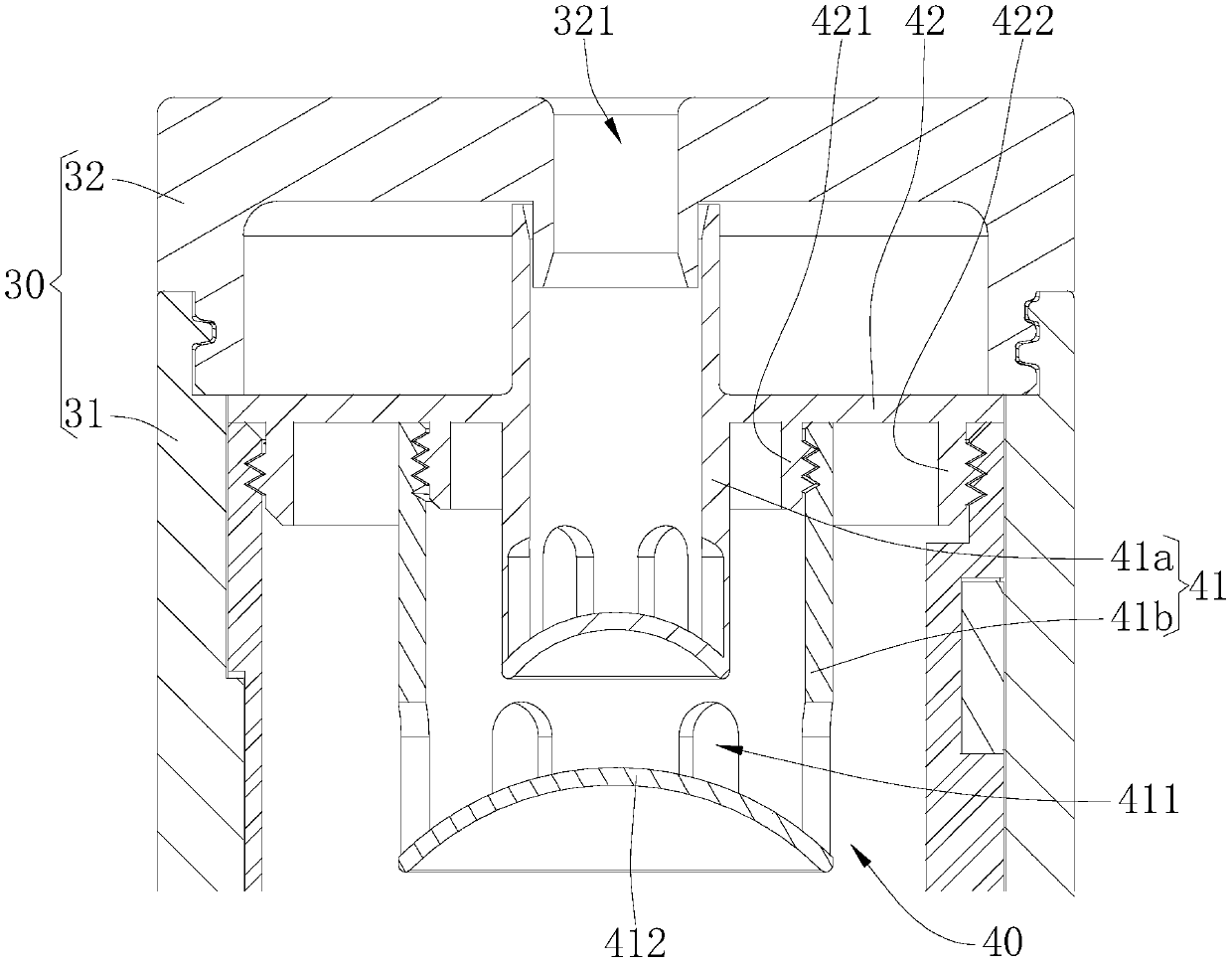
[0043] Please also refer to Figure 1 to Figure 3, the essential oil reflux atomizer provided by the present invention will now be described. The essential oil return atomizer includes a casing 10 , a casing 30 , an air pump 21 , an air pipe 22 , an air nozzle 23 , an oil nozzle 24 and a filter atomization mechanism 40 . The casing 30 is provided with an atomizing chamber 310 , and the casing 30 is provided with a mist outlet 321 connected to the atomizing chamber 310 . The lower end of the casing 30 is provided with a connection port 311 for connecting the essential oil bottle 60 . The housing 30 is installed on the casing 10 , the air pump 21 is installed in the casing 10 , and the air pump 21 is supported and protected by the casing 10 . One end of the air pipe 22 is connected with the air pump 21 , and the other end of the air pipe 22 is connected with the air nozzle 23 . The oil nozzle 24 is located at the position corresponding to the connection port 311, so that when ...

Embodiment 2

[0070] see Figure 4 and Figure 5 , the difference between the essential oil return atomizer of this embodiment and the essential oil return atomizer of Embodiment 1 is:

[0071] The side of the atomization chamber 310 facing the gas nozzle 23 is provided with a guide plate 332, the guide plate 332 is inclined to the axial direction of the outlet 231 of the gas nozzle 23, and the guide plate 332 is fixedly connected with the side wall of the atomization chamber 310. The guide plate 332 The air flow for guiding the injection of the air nozzle 23 flows upward. When the gas nozzle 23 ejects the airflow and extracts the essential oil to form a mixed airflow, the mixed airflow will flow towards the guide plate 332, and the guide plate 332 is provided to better guide the mixed airflow to the filter atomization mechanism 40, which is convenient The filter shell 41 filters the mixed air flow; at the same time, the guide plate 332 can also absorb and gather some essential oil drople...


PUM


Abstract

The invention provides an essential oil reflux-type atomizer. The atomizer includes a casing (10), a casing (30) having an atomizing chamber (310), an air pump (21), a gas pipe (22), a gas nozzle (23), and a grease nipple (24). A filter atomizing mechanism (40) is also mounted in the housing (30). The filter atomization mechanism (40) includes a plurality of filter housings (41). A plurality of through holes (411) are defined in the lower end of each filter housing (41). When the gas nozzle (23) ejects the airflow and extracts the droplets of the essential oil through the nozzle (24), the droplets of the essential oil are atomized by the airflow to form a mixed airflow, and the mixed airflow sequentially passes through the respective filter casings (41), and the droplets in the essential oil in the airflow are blocked by the respective filter shells (41) and the atomized essential oil gas is ejected through the respective through holes (411). The droplets of the essential oil at the through hole (411) are atomized again by the air flow passing through the through hole (411) to improve the atomization performance.

Description

technical field [0001] The invention belongs to the field of atomizers, and more specifically relates to an essential oil return type atomizer. Background technique [0002] Essential oils are often used in life to improve the surrounding environment or perform medical treatment; such as sterilization, disinfection, and change of environmental odors. When using essential oils, a nebulizer is used to atomize the essential oils for easy absorption by personnel or diffusion into the environment. The current essential oil nebulizers generally spray high-speed airflow through the air nozzle, suck out the essential oil in the essential oil bottle through the siphon principle, and blow it away by the high-speed airflow to achieve atomization. However, this atomization method results in larger droplets of essential oil in the atomized gas and poor atomization performance, and a large amount of essential oil is wasted when these droplets are sprayed out. Contents of the invention ...

Claims


Application Information

Patent Timeline
IPC IPC(8): B05B7/04B05B1/14B05B1/28
CPCB05B1/14B05B1/28B05B7/0491
Inventor 宋保洁
Owner PUZHEN LIFE CO LTD
Learn More