
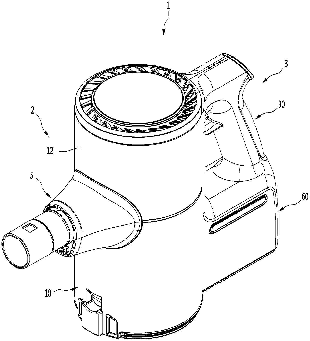
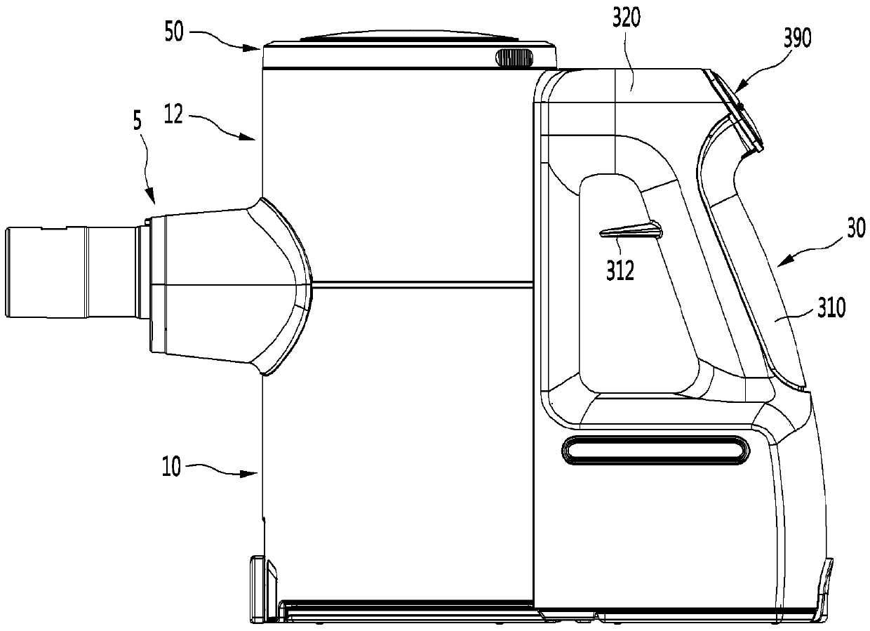
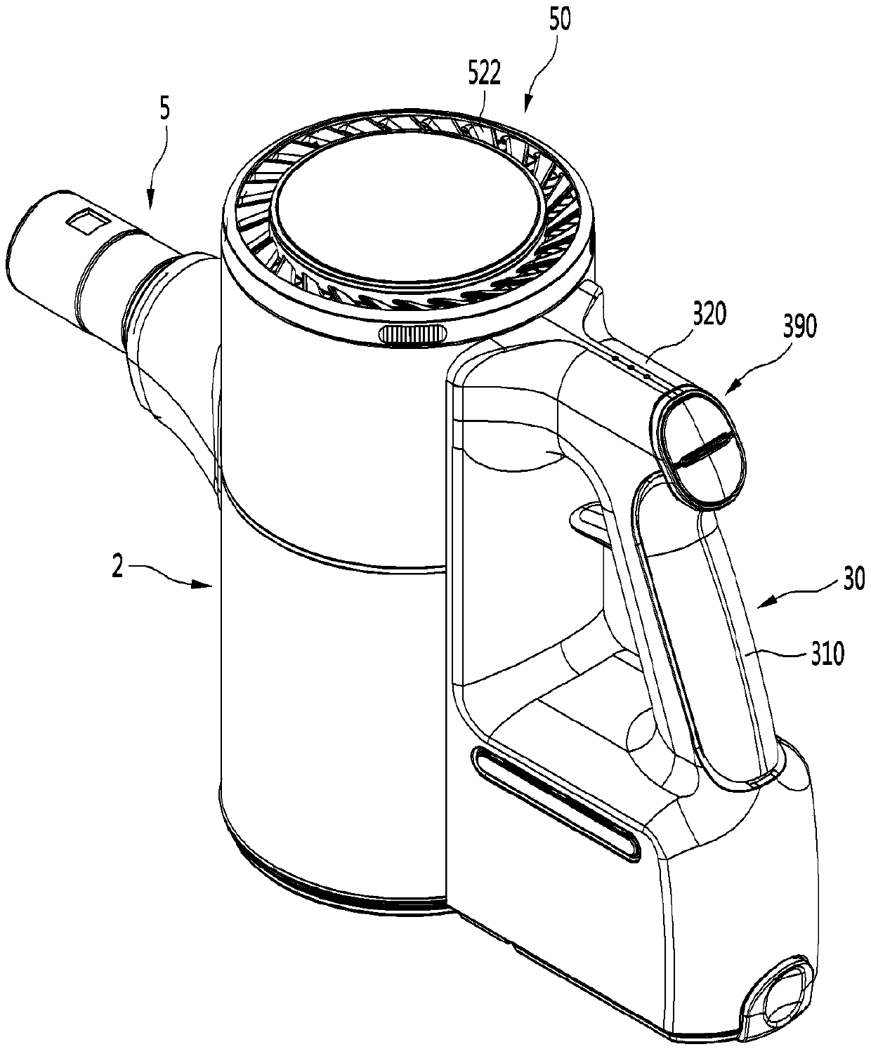
Vacuum cleaner

一种吸尘器、吸力的技术,应用在吸尘器、提供连接器和印刷电路板、耦合装置等方向,能够解决设置PCB的作业困难、结构复杂、手柄内部空间狭小等问题,达到提高连接准确性、提高结合准确性的效果

Pending Publication Date: 2019-04-16
LG ELECTRONICS INC
View PDF6 Cites 4 Cited by
  • Summary
  • Abstract
  • Description
  • Claims
  • Application Information

AI Technical Summary

Problems solved by technology

[0008] However, according to the existing literature, the airflow generator is located on the upper side of the handle, and the power supply is located on the lower side, so there is a problem that the inner space of the handle is narrow, so there is a structure for setting the PCB The problem that it becomes complicated and the work for setting up the PCB becomes difficult

Method used


Image

  • Vacuum cleaner
  • Vacuum cleaner
  • Vacuum cleaner

Examples


Embodiment Construction

[0060] Hereinafter, some embodiments of the present invention will be described in detail with exemplary drawings. It should be noted that when assigning reference signs to constituent elements in each drawing, the same reference numerals are used as much as possible even if the same constituent elements appear in different drawings. In addition, when describing the embodiments of the present invention, when it is judged that the specific description of related known structures or functions hinders the understanding of the embodiments of the present invention, the detailed description will be omitted.

[0061] In addition, terms such as first, second, A, B, (a), and (b) may be used when describing constituent elements of the embodiments of the present invention. These terms are only used to distinguish this structural element from other structural elements, and the nature, sequence, sequence, etc. of the corresponding structural elements are not limited by the terms. When it ...


PUM


Abstract

A vacuum cleaner of the present invention comprises: a main body having a suction motor for generating suction force; a main PCB capable of generating a control command for the suction motor; a handlepart capable of accommodating the main PCB; and a connector provided at the main body, and to which the main PCB is connected in a process of coupling the handle part to the main body. The main PCB includes a plurality of pads and a slit, and the connector includes: a plurality of connecting pins for making contact with the plurality of pads; and a slit insertion protrusion inserted into the slit.

Description

technical field [0001] The invention relates to a vacuum cleaner. Background technique [0002] A vacuum cleaner is a machine that performs cleaning by sucking in or wiping dust or foreign matter in an area to be cleaned. [0003] Vacuum cleaners can be divided into: manual vacuum cleaners that clean while the user directly moves the vacuum cleaner; automatic vacuum cleaners that clean while driving on their own. [0004] And, according to the shape of the vacuum cleaner, the manual vacuum cleaner may be classified into a canister vacuum cleaner, an upright vacuum cleaner, a hand-held vacuum cleaner, a stick vacuum cleaner, and the like. [0005] A portable vacuum cleaner is disclosed in Korean Patent Publication No. 10-1127088 (authorized date: March 8, 2012), which is a prior document. [0006] The portable vacuum cleaner includes a suction pipe, an airflow generator, a centrifugal separation device, a power supply and a handle. [0007] The handle may be provided with ...

Claims


Application Information

Patent Timeline
Patent Type & Authority Applications(China)
IPC IPC(8): A47L5/24A47L9/28A47L9/32A47L5/26
CPCA47L5/24A47L9/28A47L9/122A47L9/1683A47L9/22A47L9/2857A47L9/2884A47L9/2894H02J7/0045A47L9/322H01R12/7088H01R12/721H01R33/7671H01R33/955H05K1/111H05K5/003H05K5/0069H05K2201/09027H05K2201/09063H05K2201/10106
Inventor 李昌俊黄弼载黄满泰黄正培成恩智李宅基
Owner LG ELECTRONICS INC
Learn More