liquid metal restrictor
A liquid metal and current limiter technology, applied in electrical components, electrical switches, circuits, etc., can solve the problems of slow response speed and potential safety hazards of electrical equipment, and achieve the effect of fast response speed and prevention of potential safety hazards.
- Summary
- Abstract
- Description
- Claims
- Application Information
AI Technical Summary
Problems solved by technology
Method used
Image

Examples
Embodiment 1
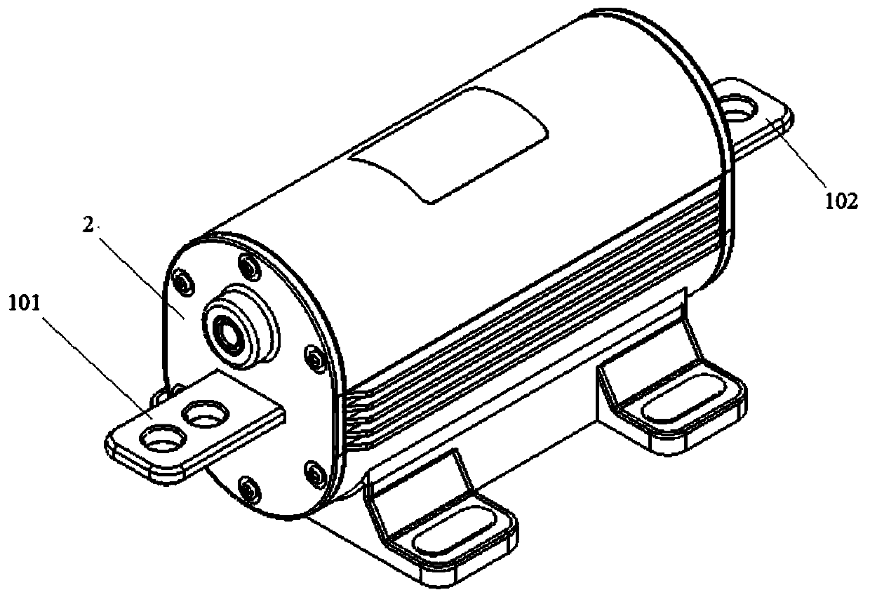
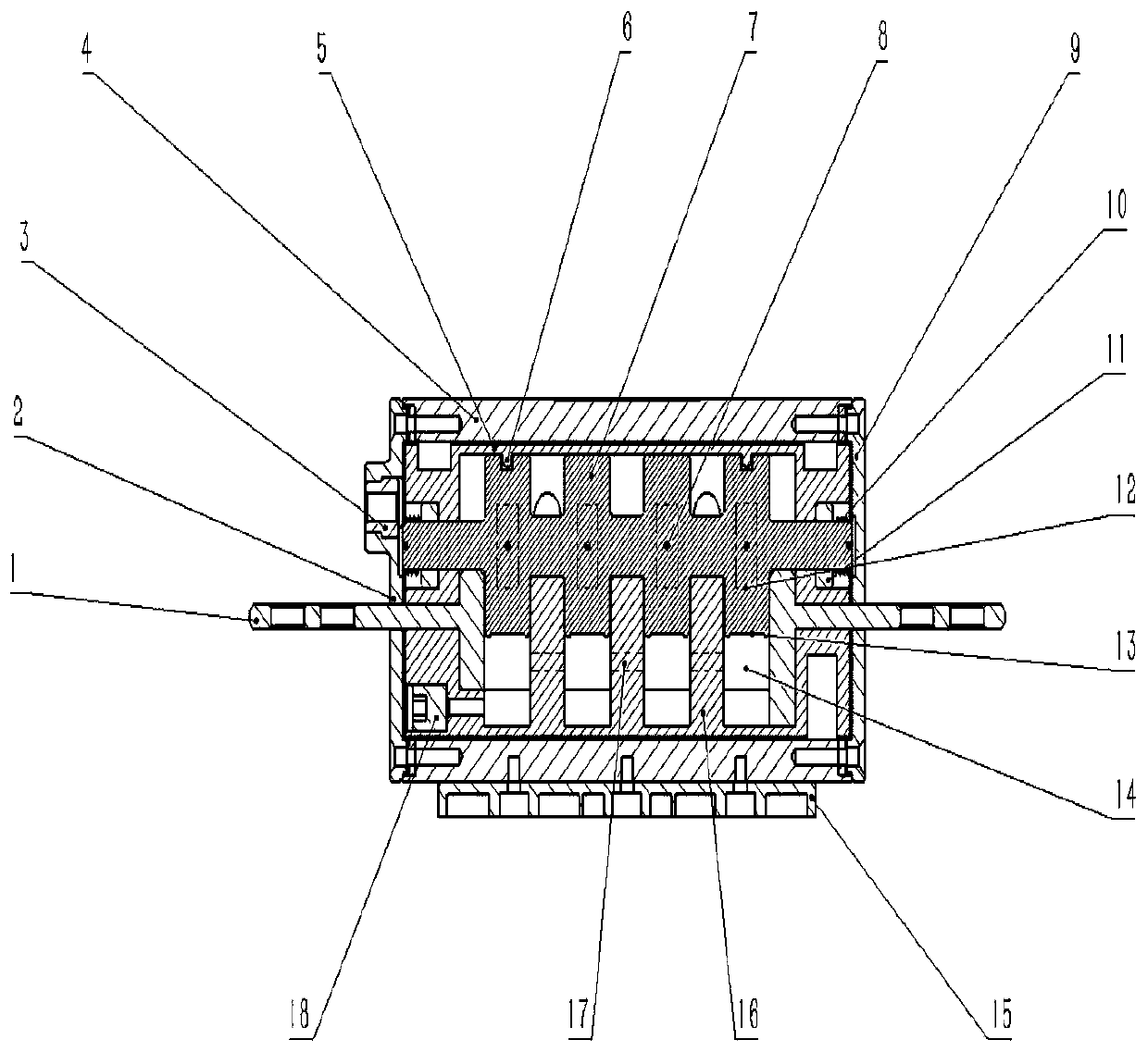
[0038] See figure 1 and figure 2 , the liquid metal current limiter of Embodiment 1 includes a casing, an electrode 1 and an insulating separator 16 . A first chamber is formed inside the casing, and liquid metal 14 is contained in the first chamber, and the electrode 1 includes a first electrode 101 and a second electrode 102, both of which extend into the first electrode 101 and the second electrode 102 from the casing. Inside a chamber, an insulating partition 16 is arranged in the first chamber and divides the first chamber into a plurality of first sub-chambers, and a through hole 17 is formed on the insulating partition 16, adjacent to the first sub-chamber They communicate with each other through the through hole 17. The first electrode 101, the second electrode 102 and the insulating barrier 16 satisfy: when the first electrode 101 and the second electrode 102 are connected to a normal circuit, a current is formed between the first electrode 101 and the second elect...
Embodiment 2
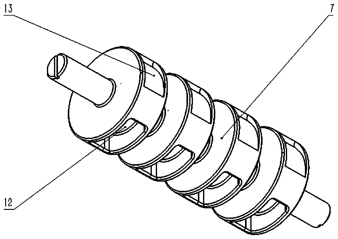
[0068] The difference from Embodiment 1 is that in Embodiment 2, a pressure sensor is provided in the first sub-chamber to measure the pressure value of the liquid metal 14 in the first sub-chamber and send it to the controller, and the controller The conversion assembly is controlled according to the pressure value. Specifically, when the pressure value is higher than the set value, the controller controls the rotating shaft 19 to rotate, and makes the accommodation tank 12 communicate with the first sub-chamber; when the pressure value is not higher than the set value, the controller controls the rotating shaft 19 to rotate , and make the accommodating tank 12 and the first sub-chamber isolated from each other.
[0069] In this case, through the cooperation between the pressure sensor and the controller, the control of the conversion component can be realized, which can realize more precise control of the liquid metal flow restrictor.
Embodiment 3
[0071] The difference from the first embodiment is that no conversion component is provided in the third embodiment. Moreover, a second chamber is also formed in the casing, and a first one-way valve (not shown in the drawings) is arranged between the second chamber and the first chamber. When the pressure of the liquid metal 14 exceeds a set value, the first one-way valve A one-way valve conducts along the direction from the first chamber to the second chamber.
[0072] In the third embodiment, through the setting of the second chamber and the first one-way valve, the pressure of the first chamber can be relieved to prevent the shell from being damaged, or the liquid metal 14 can be re-pressed into the flow hole 17 to cause the liquid metal to be limited. Streamer fails.
PUM
 Abstract
Description
Claims
Application Information
 - R&D
- Intellectual Property
- Life Sciences
- Materials
- Tech Scout
- Unparalleled Data Quality
- Higher Quality Content
- 60% Fewer Hallucinations
Browse by: Latest US Patents, China's latest patents, Technical Efficacy Thesaurus, Application Domain, Technology Topic, Popular Technical Reports.
© 2025 PatSnap. All rights reserved.Legal|Privacy policy|Modern Slavery Act Transparency Statement|Sitemap|About US| Contact US: help@patsnap.com