
Automobile exhaust purification device

A technology of automobile exhaust and purification devices, which is applied in the direction of exhaust devices, noise reduction devices, engine components, etc., can solve the problem of less involvement in particle purification, and achieve the effects of easy operation, convenient sedimentation and collection, and low price

Pending Publication Date: 2019-04-16
CHINA UNIV OF GEOSCIENCES (WUHAN)
View PDF6 Cites 0 Cited by
  • Summary
  • Abstract
  • Description
  • Claims
  • Application Information

AI Technical Summary

Problems solved by technology

[0003] At present, most automobile exhaust purification devices use the residual oxygen in the exhaust gas and the exhaust temperature to carry out redox reactions on the surface of the catalyst to convert harmful substances into non-toxic CO 2 、H 2 O and N 2 , thereby reducing the pollution to the environment, but less involved in the purification of particulate matter

Method used


Image

  • Automobile exhaust purification device
  • Automobile exhaust purification device
  • Automobile exhaust purification device

Examples


Embodiment 1

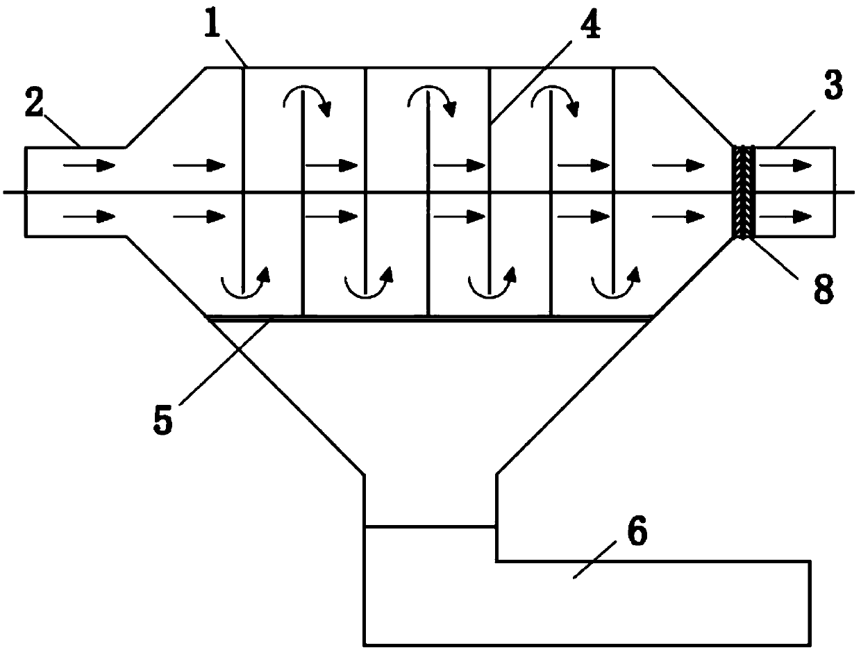
[0027] Such as figure 1 As shown, the embodiment of the present invention discloses an automobile exhaust purification device, which includes a housing 1 , an air inlet pipe 2 , an air outlet pipe 3 , a filter bag 4 , a porous sieve plate 5 , and an ash collecting hopper 6 . The air inlet pipe 2 is located at the front end of the housing 1 and is connected with the exhaust pipe of the automobile exhaust, and the outlet pipe 3 is located at the end of the housing 1 to discharge the purified automobile exhaust. The filter bag 4 is located inside the housing 1 , the porous sieve plate 5 is located below the filter bag 4 , and the dust collecting bucket 6 is located at the lower end of the housing 1 and connected with the housing 1 .

[0028] Preferably, the connection between the housing 1 and the intake pipe 2 adopts a flaring design, which is convenient for increasing the contact between the particles and the filter bag 4 after the air flow is diffused. After the automobile ex...

Embodiment 2

[0036] The difference between the second embodiment and the first embodiment is that the installation positions of the card slot 10 and the buckle 11 are different, such as Figure 6 As shown, the outer wall of the connection between the housing 1 and the ash collecting hopper 6 is provided with buckles 11, and the inner wall of the connection between the ash collecting hopper 6 and the housing 1 is provided with a slot 10, and the buckles 11 It is made of elastic material, and the inner diameter of the joint between the dust collecting hopper 6 and the housing 1 is slightly larger than the outer diameter of the joint between the housing 1 and the dust collecting hopper 6 . When installing the ash-collecting hopper 6, put the ash-collecting hopper 6 outside the casing 1 so that the buckle 11 snaps into the slot 10 to complete the connection between the casing 1 and the ash-collecting hopper 6 . When the ash collecting hopper 6 is removed, the buckle 11 is disengaged from the ...


PUM


Abstract

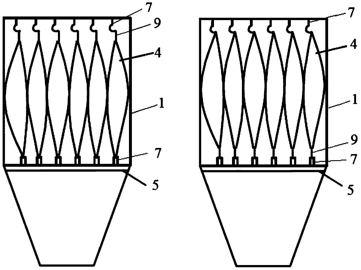
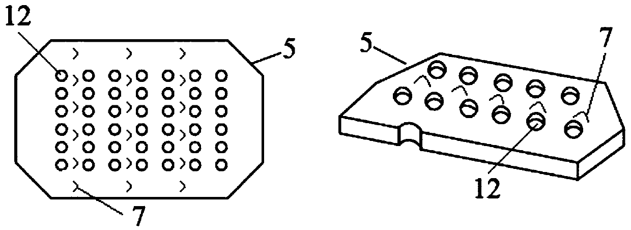
The invention discloses an automobile exhaust purification device. The automobile exhaust purification device comprises a shell body, an air inlet pipe, an air outlet pipe, a plurality of sets of filter bags, a perforated screen plate and an ash collecting hopper, wherein the air inlet pipe is located at the front end of the shell body, the air outlet pipe is located at the tail end of the shell body, the multiple sets of the filter bags are located in the shell body, the perforated screen plate is located under the filter bags, and the ash collecting hopper is located at the lower end of theshell body; each set of the filter bags comprises multiple filter bags arranged in an arrangement, each set of the filter bags is arranged in staggered mode in the shell body and the two ends of eachset of filter bags are correspondingly connected to the inner top of the shell body and the perforated screen plate; a plurality of screen holes are formed in the perforated screen plate; the ash collecting hopper is detachably connected with the shell body; and the air inlet pipe is connected with an automobile exhaust pipe, the automobile exhaust enters the shell body through the air inlet pipe,flows through the filter bags, and particulate matter carried is intercepted or stopped from settling by the filter bags into the ash collecting hopper through screen holes. According to the automobile exhaust purification device, the filter bags are used for removing the particulate matter in the automobile exhaust; and the design is reasonable, the operation is simple, materials are easy to obtain, the cost is low and the popularization and use are convenient.

Description

technical field [0001] The invention relates to the technical field of automobile exhaust purification, in particular to an automobile exhaust purification device. Background technique [0002] In recent years, haze weather characterized by fine particulate matter has become more and more common, and the problem of air pollution has attracted widespread attention. The main components of smog are sulfur dioxide, nitrogen oxides, and inhalable particulate matter. The former two are gaseous pollutants, and inhalable particulate matter is the main substance that forms smog. Research scholars at home and abroad pass the PM 2.5 Conducting source apportionment research, it was found that coal-burning sources, industrial sources, and vehicle exhaust are the sources of PM 2.5 Major emission sources with obvious contribution sources, among which motor vehicle exhaust contributes to PM 2.5 The contribution is mostly in the range of 10-30%. The vehicle exhaust mainly contains: carbo...

Claims


Application Information

Patent Timeline
Patent Type & Authority Applications(China)
IPC IPC(8): F01N3/022
CPCF01N3/022
Inventor 汪莹关林瑞田然杨雪
Owner CHINA UNIV OF GEOSCIENCES (WUHAN)
Learn More