Forming device of microstructure on inner wall of tube

A technology of microstructure and inner wall of the tube, applied in the direction of feeding device, positioning device, storage device, etc., can solve the problem of little research on manufacturing, and achieve the effect of good performance and rapid positioning and installation

Pending Publication Date: 2019-04-16
XIAMEN UNIV
View PDF0 Cites 0 Cited by
  • Summary
  • Abstract
  • Description
  • Claims
  • Application Information

AI Technical Summary

Problems solved by technology

At present, the microstructures with fluid directional flow function mainly focus on the influence of the structural characteristics of the microstructure on the fluid directional flow function, and there are very few studies on the fabrication of such functional microstructures, especially about such functional microstructures on the inner wall of the tube. Fabrication of structures has not been reported

Method used


Image

  • Forming device of microstructure on inner wall of tube
  • Forming device of microstructure on inner wall of tube
  • Forming device of microstructure on inner wall of tube

Examples


Embodiment 1

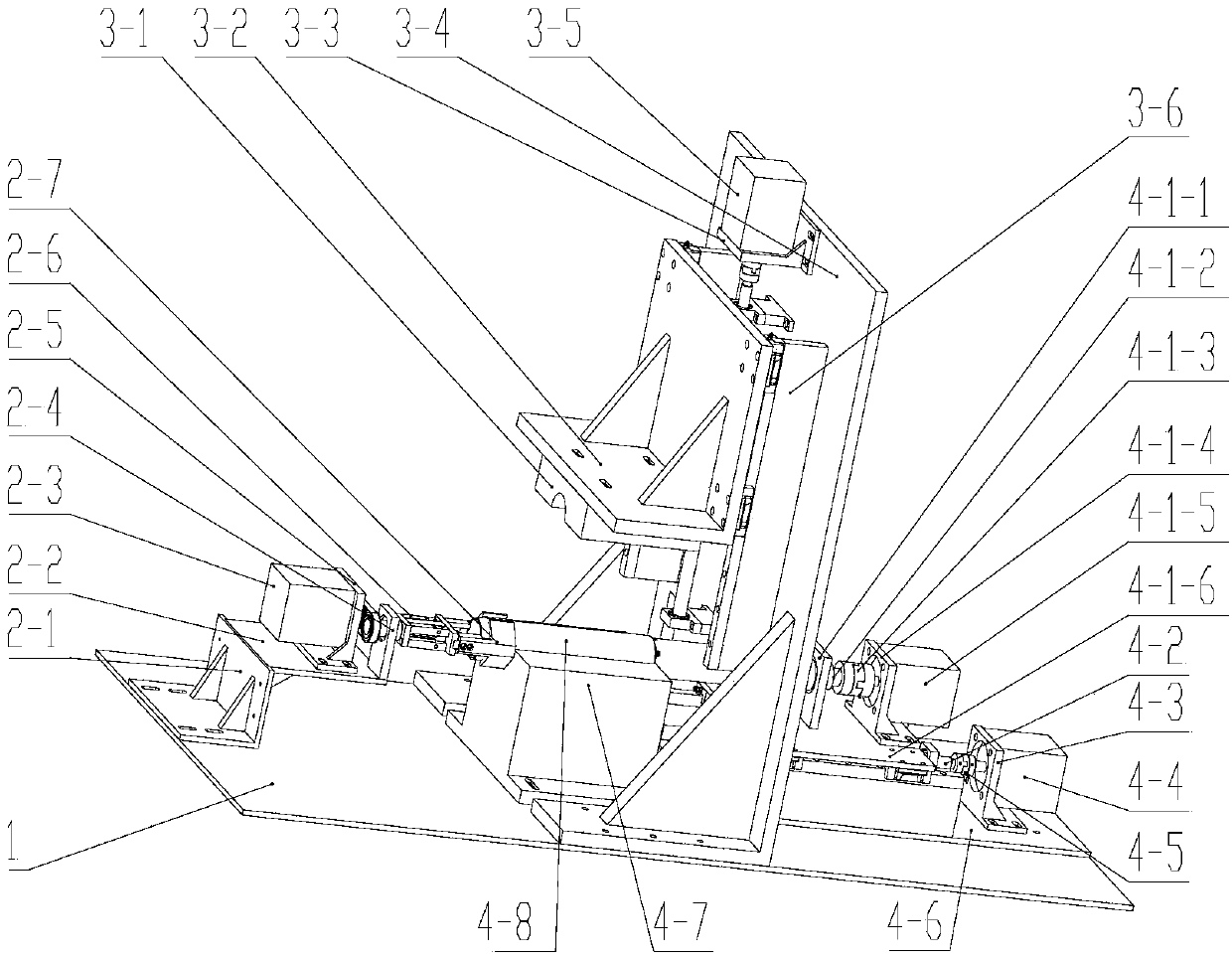
[0037] like Figure 1-19 As shown, the embodiment of the present invention is provided with a large bottom plate 1, a clamping and rotating mechanism, a pressing mechanism and a stamping and forming assembly; the clamping and rotating mechanism, a pressing mechanism and a stamping and forming assembly are fixed on the large bottom plate 1;

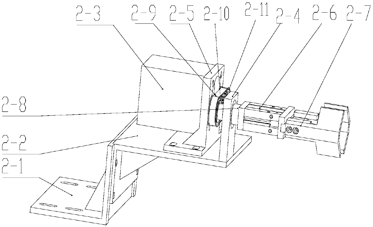
[0038] The clamping and rotating mechanism is provided with a height support seat 2-1, a first mounting seat 2-2, a first servo motor 2-3, a first bearing seat 2-4, a first motor mounting seat 2-5, a clip Tight cylinder 2-6, air claw 2-7, cylinder rotating shaft 2-8, belt 2-9, the first pulley 2-10, the second pulley 2-11;

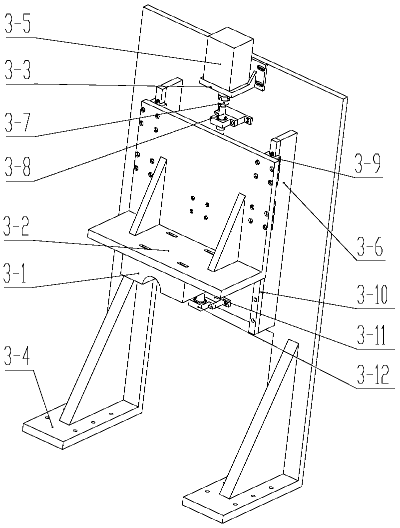
[0039] The pressing mechanism is provided with a positioning upper cover 3-1, an upper cover mounting base 3-2, a second motor mounting base 3-3, a second mounting base 3-4, a second servo motor 3-5, a first pad High seat 3-6, first coupling 3-7, first screw rod 3-8, first slider 3-9, first slide rail 3-10, bearing pa...


PUM


Abstract

The invention discloses a forming device of a microstructure on the inner wall of a tube, and relates to microstructures on the inner walls of tubes. The forming device is provided a large bottom plate, a clamping and rotating mechanism, a pressing mechanism and a stamping forming assembly, wherein the clamping and rotating mechanism, the pressing mechanism and the stamping forming assembly are fixed on the large bottom plate, the clamping and rotating mechanism is provided with a heightening supporting seat, a first mounting seat, a first servo motor, a first bearing block, a first motor mounting seat, a clamping air cylinder, a pneumatic claw, a cylinder rotating shaft, a belt and belt wheels, the pressing mechanism is provided with a positioning upper cover, an upper cover mounting seat, a second motor mounting seat, a second mounting seat, a second servo motor, a first heightening seat, a first coupler, a first screw rod, first sliding blocks, first sliding rails and a bearing heightening seat, the stamping forming assembly is provided with a stamping forming mechanism, a second screw rod, a fourth motor mounting seat, a fourth servo motor, a third coupler, a mounting plate, apositioning base, a to-be-machined part, second sliding rails, second sliding blocks, a fifth bearing block and a second heightening seat, and the stamping forming mechanism is provided with third bearing blocks, a first transmission shaft, a second coupler, a third motor mounting seat, a third servo motor, a movable plate, a fourth bearing block, a guide sleeve and a rack for stamping.

Description

technical field [0001] The present invention relates to the microstructure on the inner wall of the tube, especially relates to the microstructure on the inner wall of the tube for processing, so as to realize the microstructure on the inner wall of the tube which has the functional microstructure that can make the droplet flow directional on the surface of the microstructure. forming device. Background technique [0002] The directional movement of fluid is currently a matter of great concern. It has important applications in the design of waterproof and anti-fog materials, inkjet technology digital chips, etc. It is also of great significance to the anti-corrosion protection of power facilities and the rational use of water resources. At present, the microstructures with fluid directional flow function mainly focus on the influence of the structural characteristics of the microstructure on the fluid directional flow function, and there are very few studies on the fabricati...

Claims


Application Information

Patent Timeline
IPC IPC(8): B21D22/02B21D43/00
CPCB21D22/02B21D43/003
Inventor 周伟郑天清褚旭阳王钻开向建化万绍隆罗正钱
Owner XIAMEN UNIV
Why Eureka
Try Eureka