
Excitation system and current collector loop commutation method of excitation system

An excitation system and collector ring technology, applied in electrical components, electromechanical devices, etc., to reduce the hidden danger of collector rings and solve the effect of reverse polarity

Inactive Publication Date: 2019-04-12
沧州华润热电有限公司
View PDF4 Cites 0 Cited by
  • Summary
  • Abstract
  • Description
  • Claims
  • Application Information

AI Technical Summary

Problems solved by technology

[0003] The invention provides an excitation system and a collector ring commutation method of the excitation system, which solves the problem of reverse polarity of the collector ring without changing the excitation structure itself and does not affect the performance of the excitation structure, and reduces the current collection The hidden danger of the collector ring caused by the inconsistent wear of the positive and negative electrodes of the ring

Method used


Image

  • Excitation system and current collector loop commutation method of excitation system
  • Excitation system and current collector loop commutation method of excitation system
  • Excitation system and current collector loop commutation method of excitation system

Examples


Embodiment Construction

[0026] The present invention will be further described in detail below in conjunction with the accompanying drawings and embodiments. It should be understood that the specific embodiments described here are only used to explain the present invention, but not to limit the present invention. In addition, it should be noted that, for the convenience of description, only some structures related to the present invention are shown in the drawings but not all structures.

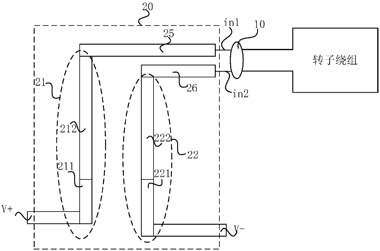
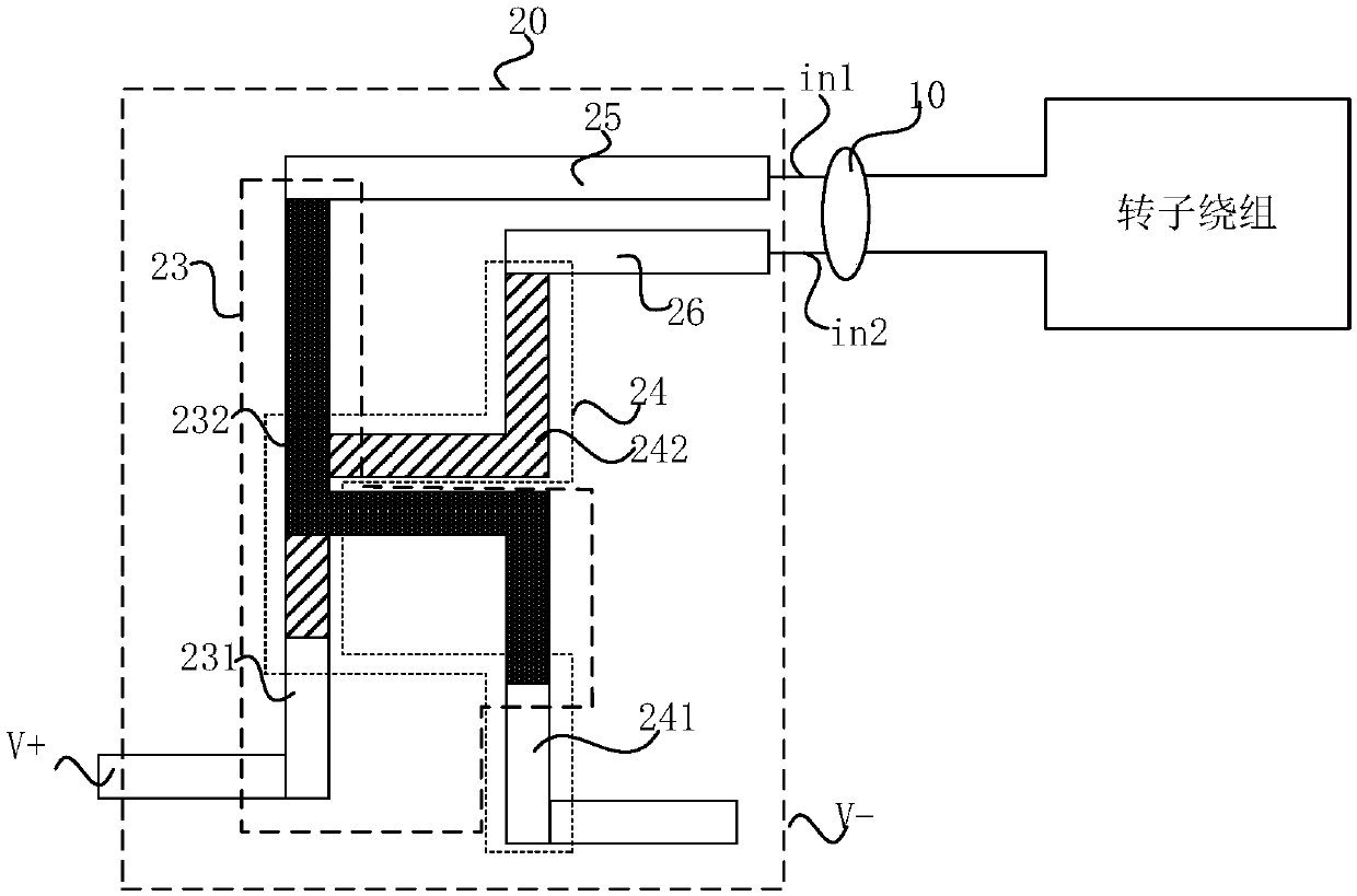
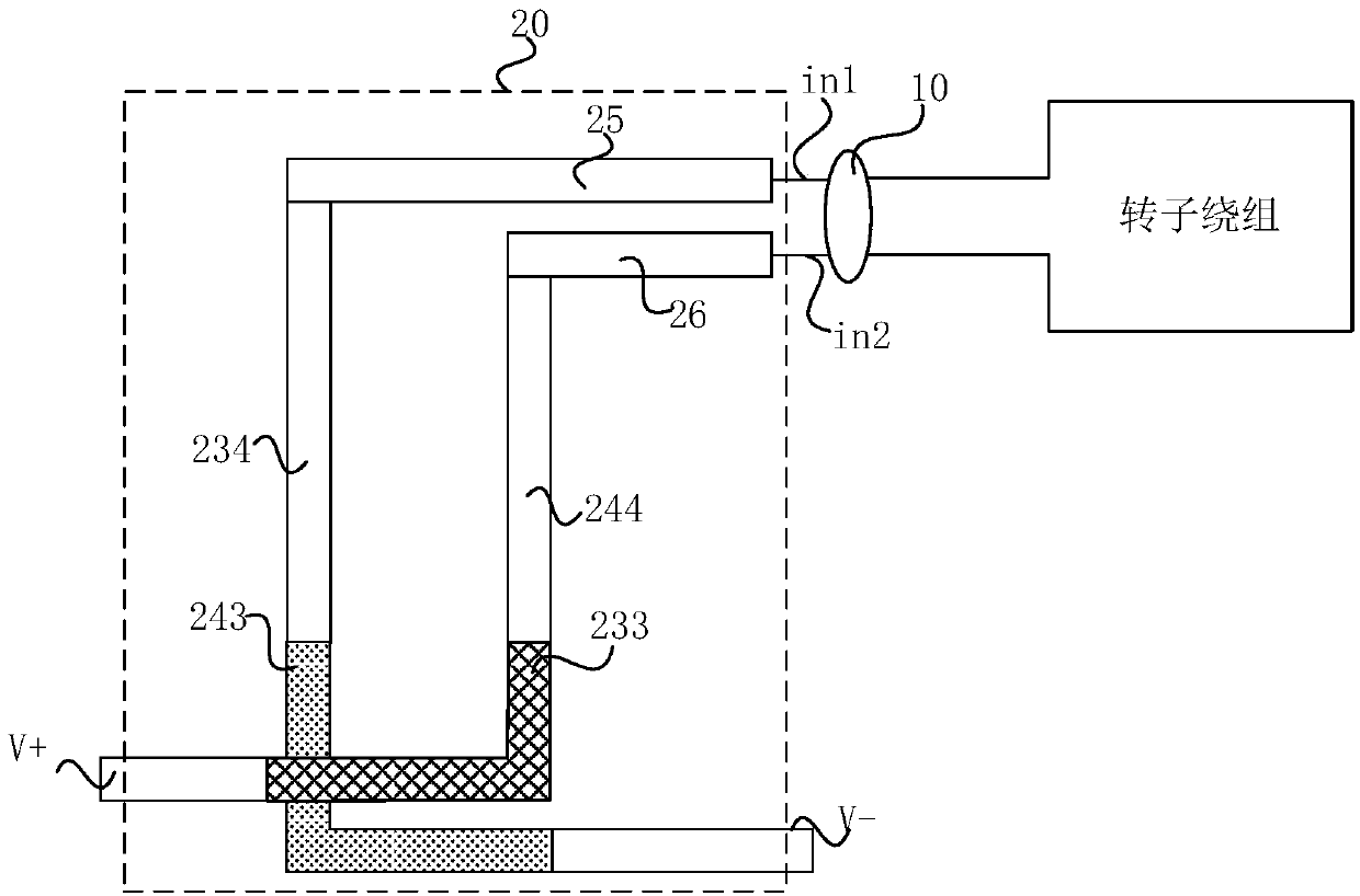
[0027] An embodiment of the present invention provides an excitation system, which includes an excitation structure, a slip ring and a connection device; the connection device includes a first connection part, a second connection part, a third connection part and a fourth connection part; the first The connecting portion is detachably electrically connected to the positive voltage output end of the excitation structure and the first input end of the slip ring, and the second connecting portion is detachably electri...


PUM


Abstract

The invention discloses an excitation system and a current collector loop commutation method of the excitation system. The excitation system comprises an excitation structure, a current collector ringand a connecting device. The connecting device comprises a first connecting part, a second connecting part, a third connecting part and a fourth connecting part. The first connection part is detachably and electrically connected with the positive voltage output terminal of the excitation structure and the first input terminal of the current collector ring, and the second connection part is detachably and electrically connected with the negative voltage output terminal of the excitation structure and the second input terminal of the current collector ring. Alternatively, the third connection portion may be detachably and electrically connected with the positive voltage output terminal of the excitation structure and the second input terminal of the current collector ring, and the fourth connection part is detachably and electrically connected with the negative voltage output terminal of the excitation structure and the first input terminal of the current collector ring. The voltage polarities of the first input terminal and the second input terminal of the current collector ring are reversed, so that the hidden danger of the current collector ring caused by the inconsistent wear ofthe positive and negative electrodes of the current collector ring is reduced without changing the excitation structure itself and affecting the performance of the excitation structure.

Description

technical field [0001] The embodiment of the present invention relates to the technical field of the slip ring of the excitation system, and in particular to an excitation system and a slip ring commutation method of the excitation system. Background technique [0002] In the prior art, the collector rings of the excitation system of 300MW and above generators cannot reverse the polarity due to the excitation structure. Under the action of current, there are electrical wear and mechanical wear in the collector ring of the generator. The polarity of the collector ring is different, and the degree of electrical wear is also different. If the collector ring is not reversed for a long time, it will inevitably cause inconsistent wear of the positive and negative poles, resulting in vibration, sparking, overheating and even burning of the collector ring, resulting in vibration, jumping of the carbon brush, and poor contact with the collector ring. Contents of the invention [0...

Claims


Application Information

Patent Timeline
IPC IPC(8): H02K13/02
Inventor 贺树棣
Owner 沧州华润热电有限公司
Learn More