A permanent magnet power-assisted double-terminal vacuum insulated grounding switch
What is Al technical title?
Al technical title is built by PatSnap Al team. It summarizes the technical point description of the patent document.
A grounding switch and vacuum insulation technology, which is applied in the field of permanent magnet assisted double-terminal vacuum insulated grounding switch, can solve the problems of poor matching of mechanical characteristics, complex structure, large space volume, etc. novel effects
Active Publication Date: 2020-05-08
BEIJING CED RAILWAY ELECTRIC TECH
View PDF3 Cites 0 Cited by
Summary
Abstract
Description
Claims
Application Information
AI Technical Summary
This helps you quickly interpret patents by identifying the three key elements:
Problems solved by technology
Method used
Benefits of technology
Problems solved by technology
In addition, the grounding switch has technical deficiencies in the development of integration and miniaturization of high-voltage electrical appliances, complex structure, large space volume, and poor matching of mechanical properties.
Method used
Image
Click on the blue label to locate the original text in one second.
Reading with bidirectional positioning of images and text.
Examples
specific Embodiment
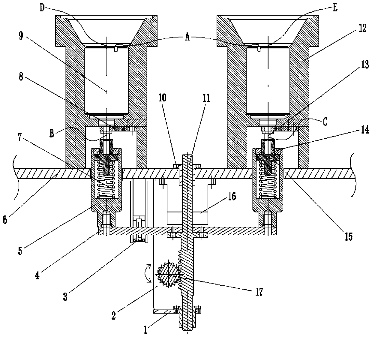
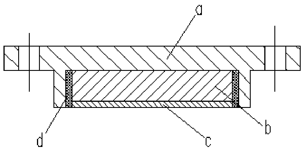
[0034] Such as figure 1 , figure 2 As shown, the permanent magnet power-assisted double-terminal vacuum insulated grounding switch of the present invention includes a positioning mounting plate 1, a mounting bracket 2, an auxiliary contact assembly 3, a synchronous connecting plate 4, an insulating pull rod 5, a base plate 6, a contact spring 7, Flexible wire 8, vacuum switch tube 9, linear bearing 10, rack shaft 11, insulating pole 12, double-ended screw rod 13, screw plug 14, connecting rod 15, gear shaft 17 and permanent magnetic chuck 16. Among them, the contact spring 7 and the connecting rod 15 are installed inside the insulating rod 5 through the screw plug 14, the insulating rod 5 passes through the base plate 6 and is fixed with the synchronous connecting plate 4, and the connecting rod 15 is connected to the flexible wire 8 through the double-ended screw rod 13 It is connected with the vacuum switch tube 9, the synchronous connecting plate 4 is fixed with the rack ...
PUM
Abstract
The invention discloses a permanent magnet power-assisted double-ended vacuum insulation earthing switch. The permanent magnet power-assisted double-ended vacuum insulation earthing switch comprises apositioning mounting plate, a mounting support, an auxiliary contact assembly, a synchronous connecting plate, an insulating pull rod, a substrate plate, a contact spring, a soft connecting line, a vacuum switch tube, a linear bearing, a rack shaft, an insulating pole, a double-thread screw, a screwed plug, a connecting rod, a gear shaft and a permanent magnet chuck, wherein the rack shaft and the gear shaft are mounted on the substrate plate through the mounting support, the positioning mounting plate and the linear bearing; the permanent magnet chuck and the auxiliary contact assembly are arranged between the substrate plate and the synchronous connecting plate; the end of the insulating pole is fixed on the substrate while the vacuum switch tube is mounted inside the insulating pole; and a vacuum degree monitoring sensor is preinstalled at the static end of the vacuum switch tube. The vacuum insulation type technology is reliable, a high-voltage fracture is closed, the journey is compact, the structure is flexible and convenient in overall arrangement, the mechanism is smart, simple and labor-saving, and the mechanical property matched thinking is novel.
Description
technical field [0001] The invention relates to the vehicle-mounted high-voltage electrical appliance technology of 25kV main line, in particular to a permanent magnet power-assisted double-terminal vacuum insulated grounding switch. Background technique [0002] The grounding switch is a very important switching device in the high-voltage electrical system of various types of electric locomotives and bullet trains with AC 25kV on the main line. It plays the role of double-terminal grounding protection of the vacuum circuit breaker of the main circuit during maintenance and emergency treatment. [0003] The vehicle-mounted grounding switch is mainly divided into three categories: manual, pneumatic and electric according to the driving mode, and the insulation form is basically the air knife switch type. Since the air insulation in a high-voltage environment needs to ensure sufficient electrical clearance, the grounding switch knife switch and vacuum There must be a certain d...
Claims
Application Information
Patent Timeline
Application Date:The date an application was filed.
Publication Date:The date a patent or application was officially published.
First Publication Date:The earliest publication date of a patent with the same application number.
Issue Date:Publication date of the patent grant document.
PCT Entry Date:The Entry date of PCT National Phase.
Estimated Expiry Date:The statutory expiry date of a patent right according to the Patent Law, and it is the longest term of protection that the patent right can achieve without the termination of the patent right due to other reasons(Term extension factor has been taken into account ).
Invalid Date:Actual expiry date is based on effective date or publication date of legal transaction data of invalid patent.