
Control equipment and system

A technology for controlling equipment and equipment, applied in general control systems, control/adjustment systems, program control, etc., can solve problems such as occupying processors, reducing processor capabilities, and multiple resources, so as to reduce resource occupancy and time jitter , the effect of fast transmission time

Pending Publication Date: 2019-04-12
GREE ELECTRIC APPLIANCES INC
View PDF0 Cites 1 Cited by
  • Summary
  • Abstract
  • Description
  • Claims
  • Application Information

AI Technical Summary

Problems solved by technology

[0002] The current robot control method mainly sends control instructions to the servo drive through the processor, and then controls the motor of the robot to realize the control of the robot. complicated
[0003] The real-time industrial Ethernet master station of the processor will occupy more resources of the processor due to real-time processing of control instructions, and the general processor usually uses serial processing, which reduces the ability of the processor, resulting in processors and robots The jitter in time between them is long, which affects the precise control of the robot

Method used


Image

  • Control equipment and system
  • Control equipment and system
  • Control equipment and system

Examples


Embodiment Construction

[0029] In order to make the purpose, technical solutions and advantages of the embodiments of the present invention clearer, the technical solutions in the embodiments of the present invention will be clearly and completely described below in conjunction with the drawings in the embodiments of the present invention. Obviously, the described embodiments It is a part of embodiments of the present invention, but not all embodiments. Based on the embodiments of the present invention, all other embodiments obtained by persons of ordinary skill in the art without making creative efforts belong to the protection scope of the present invention.

[0030] In order to facilitate the understanding of the embodiments of the present invention, further explanations will be given below with specific embodiments in conjunction with the accompanying drawings, which are not intended to limit the embodiments of the present invention.

[0031] figure 1 A structural schematic diagram of a control ...


PUM


Abstract

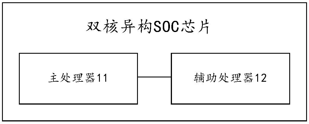
The embodiment of the invention relates to control equipment and system. The control equipment comprises a main processor and an auxiliary processor; the main processor is connected with the auxiliaryprocessor and is used for generating a control data set for controlling at least one object and sending the control data set to the auxiliary processor; and the auxiliary processor is used for performing parallel conversion processing on the control data set by using a real-time industrial Ethernet master station protocol to obtain at least one control instruction for controlling the object and sending the control instruction to the at least one object through an Ethernet interface. The real-time industrial Ethernet master station protocol runs on the auxiliary processor, the parallel processing mode of the auxiliary processor is compared with the serial processing mode of the main processor, the efficiency is higher, the real-time capability is higher, the time jitter caused by serial processing is reduced, and real-time accurate control over the object is further realized.

Description

technical field [0001] The embodiments of the present invention relate to the field of robot control, and in particular, to a control device and system. Background technique [0002] The current robot control method mainly sends control instructions to the servo drive through the processor, and then controls the motor of the robot to realize the control of the robot. It's complicated. [0003] The real-time industrial Ethernet master station of the processor will occupy more resources of the processor due to real-time processing of control instructions, and the general processor usually uses serial processing, which reduces the ability of the processor, resulting in processors and robots The time jitter between them is long, which affects the precise control of the robot. Contents of the invention [0004] In view of this, in order to solve the above technical problems or part of the technical problems, embodiments of the present invention provide a control device and sy...

Claims


Application Information

Patent Timeline
Patent Type & Authority Applications(China)
IPC IPC(8): G05B19/042
CPCG05B19/0423G05B2219/24215
Inventor 胡飞鹏胡余生钟成堡王长恺殷伟豪
Owner GREE ELECTRIC APPLIANCES INC
Learn More