


Quick Research
Generate reliable direction feasibility study reports for your R&D in just a few steps.

Technical Q&A
Discover and master advanced knowledge NOW. Basics, ideas, possibilities, all at once.

Find Solutions
As an expert in R&D theories, this can generate solutions to your technical problems instantly.

Evaluate Feasibility
Analyze your overall solution with one click, know your potential R&D risks in advance.

Monitor Landscape
Get weekly tech updates, stay abreast of the latest tech innovations and key insights.
Scribing and cutting device for beam intensity meter and its application
A beam intensity meter and cutting rod technology, applied in measuring devices, using stable tension/pressure to test material strength, instruments, etc., can solve the problems of inaccurate cutting, troublesome operation, large error fluctuation, etc., to achieve measurement and calculation. Accurate, easy to use and install the mechanism, accurate cutting process
- Summary
- Abstract
- Description
- Claims
- Application Information
AI Technical Summary
Problems solved by technology
Method used
Image

Examples
Embodiment 1
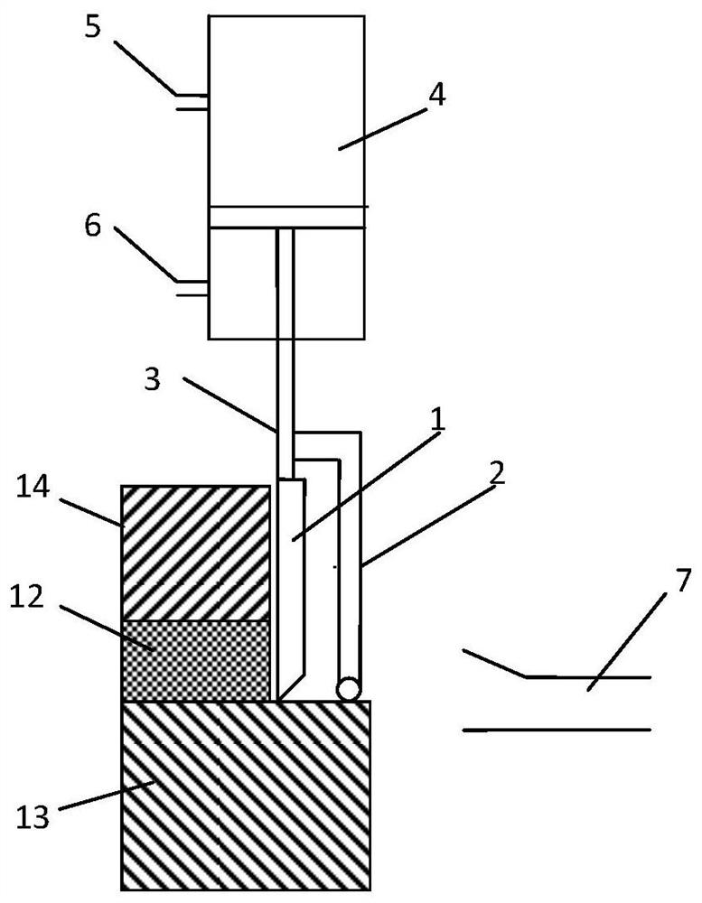
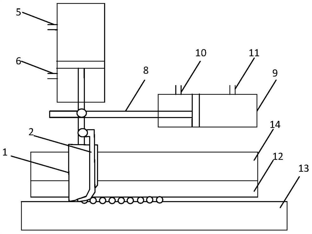
[0027] The embodiment uses 66 combed wool (2114 μm) to test. Environmental conditions of the experiment: the temperature is 20° C., and the relative humidity is 65%. First, the cutting cylinder 9 is positioned at the initial position, and the bundle of fibers is clamped between the upper chuck 12 and the lower chuck 13 at a fixed distance, and the two ends of the grown fibers are laid parallel and straight on the lower chuck 13, and the cylinder 4 The air valve 5 intakes air, making the cutter 1 and the pressing rod 2 drop until the pressing rod 2 presses the head end of the fiber bundle; the cutting valve 10 of the cutting cylinder 9 intakes air, so that the cutting knife 1 and the pressing rod 2 move toward the uncut fiber direction , the pressing rod 2 compresses the fiber before the cutter 1 cuts the fiber, and then gradually cuts off the wool bundle fiber.
Embodiment 2
[0029] Embodiment Adopt ramie (fineness is 0.9tex, length is 36.2mm) test. Environmental conditions of the experiment: the temperature is 20° C., and the relative humidity is 65%. First, the cutting cylinder 9 is positioned at the initial position, and the bundle of fibers is clamped between the upper chuck 12 and the lower chuck 13 at a fixed distance, and the two ends of the grown fibers are laid parallel and straight on the lower chuck 13, and the cylinder 4 The air valve 5 intakes air, making the cutter 1 and the pressing rod 2 drop until the pressing rod 2 presses the head end of the fiber bundle; the cutting valve 10 of the cutting cylinder 9 intakes air, so that the cutting knife 1 and the pressing rod 2 move toward the uncut fiber direction , the pressing rod 2 compresses the fiber before the cutter 1 cuts the fiber, and then gradually cuts off the ramie bundle fiber.
Embodiment 3
[0031] The embodiment adopts carbon fiber 2.2K test. Environmental conditions of the experiment: the temperature is 20° C., and the relative humidity is 65%. First, the cutting cylinder 9 is positioned at the initial position, and the bundle of fibers is clamped between the upper chuck 12 and the lower chuck 13 at a fixed distance, and the two ends of the grown fibers are laid parallel and straight on the lower chuck 13, and the cylinder 4 The air valve 5 intakes air, making the cutter 1 and the pressing rod 2 drop until the pressing rod 2 presses the head end of the fiber bundle; the cutting valve 10 of the cutting cylinder 9 intakes air, so that the cutting knife 1 and the pressing rod 2 move toward the uncut fiber direction , the pressing rod 2 compresses the fiber before the cutter 1 cuts the fiber, and then gradually cuts off the carbon bundle fiber.
PUM
 Abstract
Description
Claims
Application Information
 - R&D Engineer
- R&D Manager
- IP Professional
- Industry Leading Data Capabilities
- Powerful AI technology
- Patent DNA Extraction
Browse by: Latest US Patents, China's latest patents, Technical Efficacy Thesaurus, Application Domain, Technology Topic, Popular Technical Reports.
© 2024 PatSnap. All rights reserved.Legal|Privacy policy|Modern Slavery Act Transparency Statement|Sitemap|About US| Contact US: help@patsnap.com