
Hybrid new energy power generation device

A power generation device and new energy technology, which is applied in the field of hybrid new energy power generation devices, can solve the problems of occupying a large space, low energy conversion rate, and low conversion rate

Inactive Publication Date: 2019-04-12
贵州西能电力建设有限公司
View PDF6 Cites 1 Cited by
  • Summary
  • Abstract
  • Description
  • Claims
  • Application Information

AI Technical Summary

Problems solved by technology

[0003] Existing new energy power generation devices usually use solar photovoltaic panels to absorb light energy, but the energy conversion rate is low. In the actual application process, it is necessary to lay a large area of ​​photovoltaic panels, which will occupy a large space. At the same time, solar photovoltaic power generation has time Due to the limitations of the environment, it will stop working when there is a lack of light at night, and it cannot work around the clock. This single-use solar photovoltaic panel cannot meet the needs of people. In addition, the wind energy of the hybrid power generation equipment that combines wind energy and solar energy Interference between the generator set and the solar photovoltaic panel is easy to occur. When the angle of the solar panel is changed, it is easy to interfere with the wind energy generator set. It cannot effectively convert light energy and wind energy into electrical energy, making the conversion rate not high. Therefore, when using In the process, it has brought a certain impact. Therefore, we propose a hybrid new energy power generation device

Method used


Image

  • Hybrid new energy power generation device
  • Hybrid new energy power generation device
  • Hybrid new energy power generation device

Examples


Embodiment Construction

[0027] The following will clearly and completely describe the technical solutions in the embodiments of the present invention with reference to the accompanying drawings in the embodiments of the present invention. Obviously, the described embodiments are only some, not all, embodiments of the present invention. Based on the embodiments of the present invention, all other embodiments obtained by persons of ordinary skill in the art without making creative efforts belong to the protection scope of the present invention.

[0028] In the description of the present invention, it should be noted that the terms "center", "upper", "lower", "left", "right", "vertical", "horizontal", "inner", "outer" etc. The indicated orientation or positional relationship is based on the orientation or positional relationship shown in the drawings, and is only for the convenience of describing the present invention and simplifying the description, rather than indicating or implying that the referred d...


PUM


Abstract

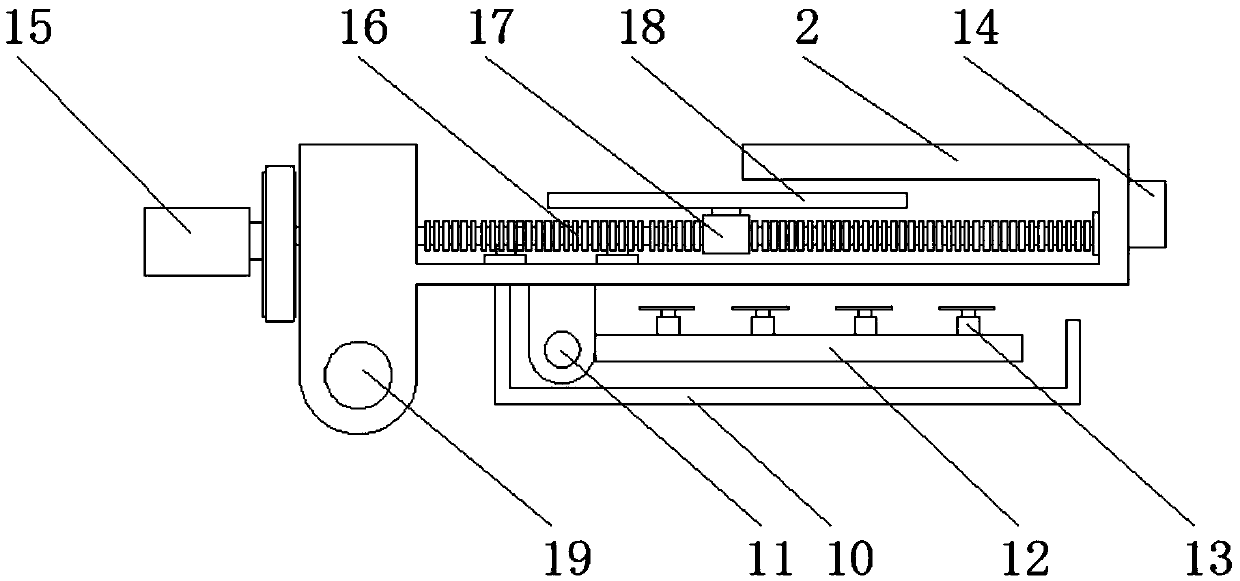
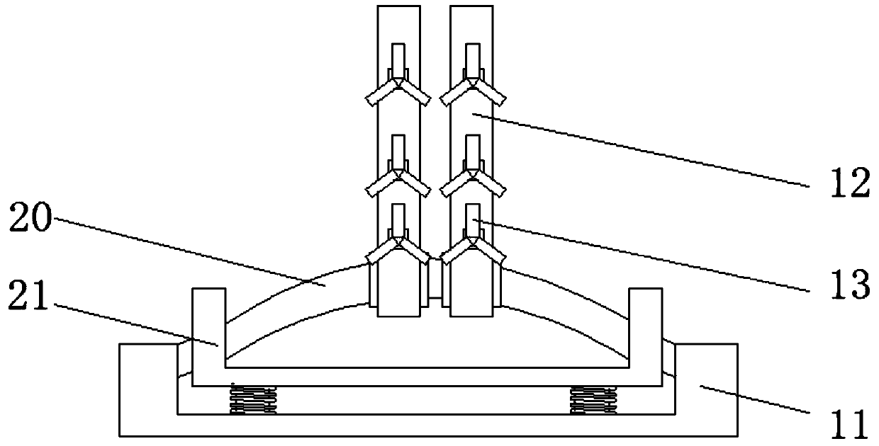
The invention discloses a hybrid new energy power generation device which comprises a base. Supporting plates are hinged to one end of the outer surface of the top of the base. A storage battery set is fixedly mounted on the outer surface of the top of the base. A center column is welded to the side, close to the storage battery set, of the outer surface of the top of the base. First fixed blocksare fixed to the outer surface of the center column. A telescopic rod is hinged to the end, close to the corresponding supporting plate, of each first fixed block. A generator is fixedly connected tothe end, away from the storage battery set, of the center column. A main shaft is welded to the side wall of the side, away from the storage battery set, of the generator. A wind wheel device is in bolted connection to the outer surface of the main shaft. According to the hybrid new energy power generation device, wind energy and solar energy are combined for power generation, and overall continuous operation can be carried out; and in addition, interference can be reduced to a certain degree, the new energy conversion rate can be increased, and better application prospects can be brought.

Description

technical field [0001] The invention relates to the field of power generation devices, in particular to a hybrid new energy power generation device. Background technique [0002] With the limitation of conventional energy and the increasingly prominent environmental problems, economic development and social progress are inseparable from energy. Finding available energy has become the direction of scientific research. New energy is becoming more and more environmentally friendly and renewable. New energy includes all renewable resources that can be developed and utilized on the basis of technology, including solar energy, biomass energy, wind energy, geothermal energy, tidal energy and other renewable resources. At present, solar photovoltaic power generation technology is becoming more and more mature. It has become the most widely used new energy. At the same time, the use of new energy to generate electricity is the most widely used method of new energy, that is, the use o...

Claims


Application Information

Patent Timeline
IPC IPC(8): F03D9/11F03D13/20H02S10/12H02S20/30
CPCF03D9/007F03D9/11F03D13/20H02S10/12H02S20/30Y02E10/50Y02E10/72Y02E10/728Y02E70/30
Inventor 王金芳
Owner 贵州西能电力建设有限公司
Learn More