Template machine for clothing
A template machine and machine body technology, applied in the direction of cloth feeding mechanism, sewing machine components, textiles and papermaking, etc., can solve the problems of poor heat dissipation performance, high body heat, shortened service life, etc., to improve heat dissipation effect, improve heat dissipation efficiency, improve The effect of heat dissipation
- Summary
- Abstract
- Description
- Claims
- Application Information
AI Technical Summary
Problems solved by technology
Method used
Image
Examples
Embodiment 1
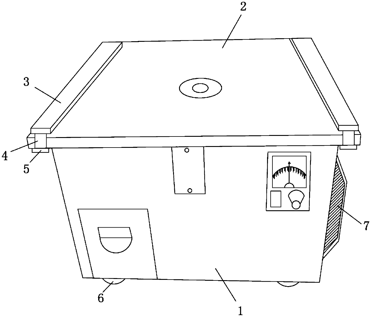
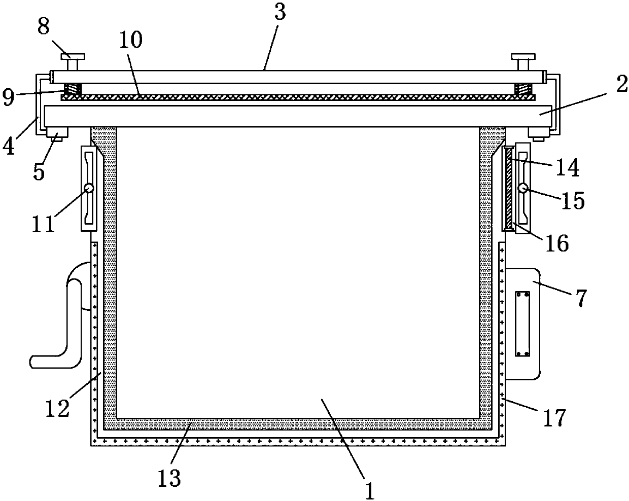
[0025] Such as Figure 1-2 As shown, a garment template machine includes a body 1 and a workbench 2, the workbench 2 is located on the upper part of the body 1, a cooling pipe 12 is installed on the inner wall of the body 1, and a ventilation fan is installed on one side of the upper part of the body 1 11, and the other side of the upper part of the body 1 is provided with a cooling pipeline 16, the ventilation fan 11 communicates with the cooling pipeline 16 through the heat dissipation pipeline 12, the inner wall of the heat dissipation pipeline 12 is inlaid with a water cooling tube 17, and the bottom of the body 1 is fixed on the outside Connect the water-cooling radiator 7, the water-cooling radiator 7 and the water-cooling pipe 17 are connected to each other, the cooling fin 14 is installed inside the cooling pipeline 16, and the blowing fan 15 is clamped on the outer side of the cooling pipeline 16.
[0026] In this embodiment, since a heat dissipation pipe is installed...
Embodiment 2
[0028] Such as Figure 1-2 As shown, the bottom of both ends of the workbench 2 are welded with card slots 5, both ends of the workbench 2 are provided with U-shaped clamping columns 4, the upper part of the workbench 2 is provided with a connecting plate 3, and the U-shaped One end of the clamping column 4 is clamped to the connecting plate 3, and the other end of the U-shaped clamping column 4 is clamped to the card slot 5. Both ends of the connecting plate 3 are slidably connected to the connecting rod 8, and the bottom of the connecting plate 3 is provided with a pressure rod 10 , the connecting rod 8 passes through the connecting plate 3 and is fixedly connected to the pressing rod 10 , the outer bottom side of the connecting rod 8 is provided with a spring 9 , and the spring 9 is located between the connecting plate 3 and the pressing rod 10 .
[0029] In this embodiment, the U-shaped post 4 and the pressure bar 10 are provided to facilitate the fixing of the garment tem...
Embodiment 3
[0031] Such as Figure 1-3 As shown, the inner side of the heat dissipation pipe 12 is equipped with a noise reduction interlayer 13, the noise reduction interlayer 13 is composed of a centrifugal glass wool interlayer 19 and a polyester fiber sound-absorbing interlayer 20, and the centrifugal glass wool interlayer 19 is located on the polyester fiber sound-absorbing interlayer 20, the centrifugal glass wool interlayer 19 and the polyester fiber sound-absorbing interlayer 20 are inlaid with a heat-conducting silica gel layer 18, and both ends of the bottom of the body 1 are equipped with universal wheels 6.
[0032] In this embodiment, the noise-reducing interlayer 13 is provided to effectively improve the noise-reducing performance of the body 1 and avoid noise disturbance and damage.
[0033] It should be noted that the present invention is a garment template machine. When working, connect the device to the power supply. When the internal heat of the body 1 is too high, turn...
PUM
 Abstract
Description
Claims
Application Information
 - R&D Engineer
- R&D Manager
- IP Professional
- Industry Leading Data Capabilities
- Powerful AI technology
- Patent DNA Extraction
Browse by: Latest US Patents, China's latest patents, Technical Efficacy Thesaurus, Application Domain, Technology Topic, Popular Technical Reports.
© 2024 PatSnap. All rights reserved.Legal|Privacy policy|Modern Slavery Act Transparency Statement|Sitemap|About US| Contact US: help@patsnap.com


