A micro-nano structure that can generate circular dichroism
A technology of micro-nano structure and circular dichroism, applied in the field of micro-nano optics, can solve the problems of weak circular dichroism and high requirements for detection instruments, and achieve the effect of strong circular dichroism
- Summary
- Abstract
- Description
- Claims
- Application Information
AI Technical Summary
Problems solved by technology
Method used
Image

Examples
Embodiment 1
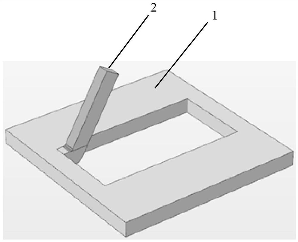
[0029] This embodiment discloses a micro-nano structure that can produce circular dichroism. The micro-nano structure is composed of multiple unit structures connected to each other in a rectangular periodic array, such as figure 1 Each unit structure includes a rectangular hollow metal ring 1 and a metal strip 2, one end of the metal strip 2 is connected to the rectangular corner of the hollow metal ring 1 or the non-midpoint of the short side of the hollow metal ring, and the other end is connected to the hollow metal ring 1 The plane where the metal strip 2 and the hollow metal ring 1 are located has a characteristic angle α, and the characteristic angle α is not equal to 0°, 90° or 180°; the hollow metal ring 1 is a rectangular ring; the metal strip is a rectangular strip or " L"-shaped bar; both the metal bar 2 and the hollow metal ring 1 are made of precious metal materials.
[0030] in particular:
[0031] The inner ring of the hollow metal ring 1 can be in any shape, ...
Embodiment 2
[0042] Based on the micro-nano structure disclosed in Example 1, this embodiment further discloses a micro-nano structure that can produce circular dichroism. The difference from Example 1 is that, as Figure 5 As shown, there is a slit between the metal strip 2 and the rectangular hollow metal ring 1 .
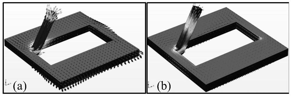
[0043] Specifically: the metal strip 2 is connected to one side of the hollow metal ring 1 and separated from the other three sides. When left-handed polarized light irradiates the micro-nano structure of this embodiment, the slit between the metal strip 2 and the rectangular hollow metal ring 1 strengthens the flow current on the metal strip 2, and forms a Circulation, the coupling between the two makes the micro-nano structure of this embodiment absorb the left-handed polarized light greatly, thereby enhancing the circular dichroism of the micro-nano structure of this embodiment.
[0044] In this embodiment, the current distribution of the micro-nano structure is as follow...
Embodiment 3
[0047] Based on the micro-nano structure disclosed in the embodiment, this embodiment further discloses a micro-nano structure capable of producing circular dichroism. The difference from embodiment 1 is that there are no less than two metal strips 2 connected to the hollow metal The two opposite sides of ring 1, such as Figure 9 As shown, there are preferably two metal strips 2 in this embodiment, which are respectively arranged on two opposite sides of the rectangular ring.
[0048] The electric field distribution diagram of the micro-nano structure in this embodiment is as follows Figure 10 as shown, Figure 10 (a) is the current distribution diagram of the micro-nano structure irradiated by the left-handed light of the wavelength λ=820nm mode, Figure 10 (b) is the current distribution diagram of the micro-nano structure irradiated by the right-handed light of the wavelength λ=820nm mode, Figure 10 (c) is the current distribution diagram of the micro-nano structure i...
PUM
 Abstract
Description
Claims
Application Information
 - Generate Ideas
- Intellectual Property
- Life Sciences
- Materials
- Tech Scout
- Unparalleled Data Quality
- Higher Quality Content
- 60% Fewer Hallucinations
Browse by: Latest US Patents, China's latest patents, Technical Efficacy Thesaurus, Application Domain, Technology Topic, Popular Technical Reports.
© 2025 PatSnap. All rights reserved.Legal|Privacy policy|Modern Slavery Act Transparency Statement|Sitemap|About US| Contact US: help@patsnap.com