
Infrared detector with high-efficiency resonant cavity and preparation method thereof

An infrared detector and resonant cavity technology, applied in the field of photoelectric detection, can solve the problems of weakening the infrared signal and affecting the detection efficiency of the detector, and achieve the effects of easy formation, improving the utilization rate of the infrared signal, and low sensitivity

Inactive Publication Date: 2019-04-09
XIAN TECHNOLOGICAL UNIV
View PDF17 Cites 6 Cited by
  • Summary
  • Abstract
  • Description
  • Claims
  • Application Information

AI Technical Summary

Problems solved by technology

However, in order to further improve device integration, when other silicon-based detection structures are superimposed on the infrared detector, the infrared signal received by the infrared sensitive film is weakened due to the inevitable absorption of infrared light in the process of penetrating the upper material, thus affecting The detection efficiency of the detector

Method used


Image

  • Infrared detector with high-efficiency resonant cavity and preparation method thereof
  • Infrared detector with high-efficiency resonant cavity and preparation method thereof
  • Infrared detector with high-efficiency resonant cavity and preparation method thereof

Examples


Embodiment Construction

[0043] The present invention is described in further detail below in conjunction with accompanying drawing:

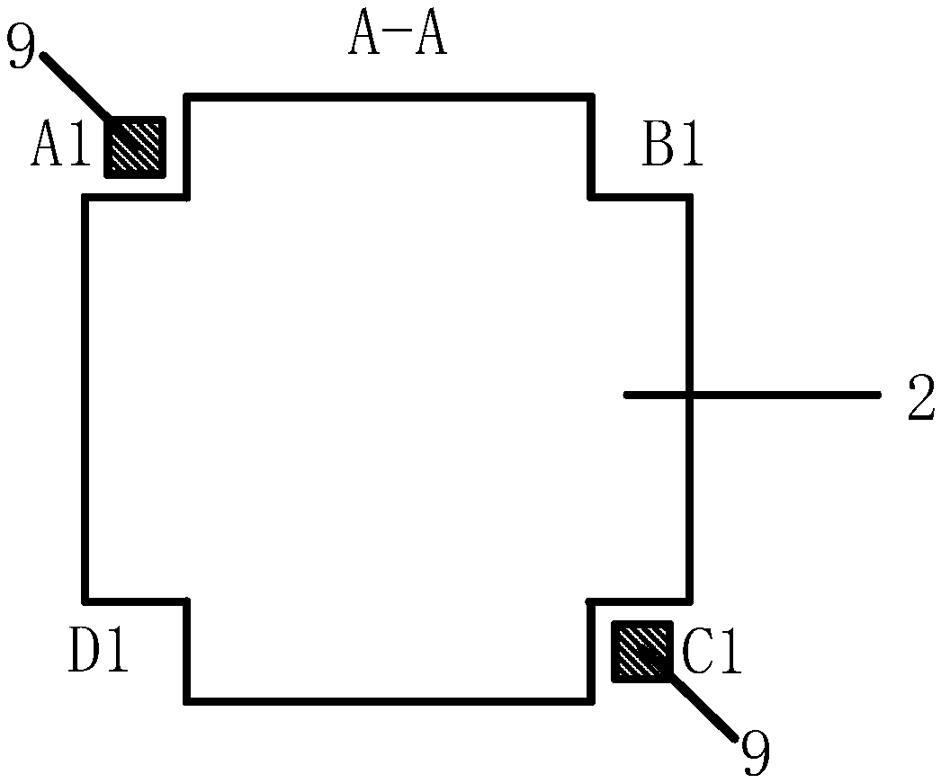
[0044] see figure 1 and figure 2 , the invention discloses an infrared detector with a high-efficiency resonant cavity and a preparation method thereof. The infrared detector includes an upper substrate 1 and a lower substrate 5, and an upper reflective layer 2 is provided on the lower surface of the upper substrate 1 , the upper surface of the lower substrate 5 is provided with a lower reflective layer 4, the upper reflective layer 2 of each detector unit has the same shape and size as the lower reflective layer 4, and its material is metal, and the thickness of the upper reflective layer 2 is 5-50nm , between the upper substrate 1 and the upper reflective layer 2 is provided with an upper chromium thin film 12, the thickness of the upper chromium thin film 12 is 1 / 10 of the thickness of the upper reflective layer 2; the thickness of the lower reflective layer 4 is ...


PUM


Abstract

The present invention discloses an infrared detector with a high-efficiency resonant cavity and a preparation method thereof. In order to improve the integration degree of the chip, the resonant cavity of the detector is arranged inside the silicon wafer, and compared with the conventional infrared detecting device, the vacuum chamber of the sensitive film is only a few micrometers in height, thecavity space is greatly reduced, a high vacuum is formed and maintained in an easier manner, and the heat loss of the sensitive layer caused by air convection can be avoided. The sensitive layer filmis arranged in the middle of the resonant cavity, and the upper reflective layer is a thin metal layer which is half-transflected on the back surface of the upper substrate; and the lower reflective layer is a thick metal layer which is totally reflected on the upper surface of the lower substrate, and the light reflects in a round trip in the resonant cavity to pass through the sensitive layer film for two times, so that the number of times of passing through the sensitive layer film is increased, and the light absorption rate is increased. The preparation method for the resonant cavity reflective layer is a conventional photolithography, coating and etching process, the process is simple and easy to implement, the metal pillars are respectively fabricated on the two substrates and finally assembled into a resonant cavity by flip chip bonding, and a skillful process, a low cost and high precision are achieved.

Description

【Technical field】 [0001] The invention belongs to the technical field of photoelectric detection, and in particular relates to an infrared detector with a high-efficiency resonant cavity and a preparation method thereof. 【Background technique】 [0002] The infrared imaging system is a system that relies on the thermal radiation of the target and the background to generate a scene image. It can work 24 hours a day, and can detect hidden thermal targets through camouflage. The infrared detector is the core component of the infrared imaging system, which can convert the incident infrared signal into an electrical signal output by the photoelectric effect and pyroelectric effect. However, in order to further improve device integration, when other silicon-based detection structures are superimposed on the infrared detector, the infrared signal received by the infrared sensitive film is weakened due to the inevitable absorption of infrared light in the process of penetrating the u...

Claims


Application Information

Patent Timeline
Patent Type & Authority Applications(China)
IPC IPC(8): G01J5/20G01J5/02
CPCG01J5/024G01J5/20
Inventor 刘卫国王卓曼刘欢韩军周顺解潇潇安妍
Owner XIAN TECHNOLOGICAL UNIV
Learn More