Variable cycle high bypass ratio turbofan engine

A turbofan engine, high bypass ratio technology, applied in the direction of engine components, machines/engines, mechanical equipment, etc., can solve the problems of limited engine life, high combustion chamber outlet temperature, limited thrust margin development, etc. The effect of avoiding energy loss, increasing service life and reducing total temperature

Active Publication Date: 2021-10-19
AECC COMML AIRCRAFT ENGINE CO LTD
View PDF7 Cites 0 Cited by
  • Summary
  • Abstract
  • Description
  • Claims
  • Application Information

AI Technical Summary

Problems solved by technology

[0008] The technical problem to be solved by the present invention is to overcome the high temperature of the outlet of the combustion chamber, the limited development of the thrust margin and the limited life of the engine under the ground take-off and climb state of the turbofan engine in the prior art, and the variable bypass ratio also brings In order to overcome defects such as the working mismatch of the supercharging stage, a variable cycle turbofan engine with a large bypass ratio is provided, which combines the variable turbine guide vane and the adjustable guide vane of the supercharging stage to coordinate operation, and changes the bypass ratio of the aeroengine in real time

Method used


Image

  • Variable cycle high bypass ratio turbofan engine
  • Variable cycle high bypass ratio turbofan engine
  • Variable cycle high bypass ratio turbofan engine

Examples


Embodiment 1

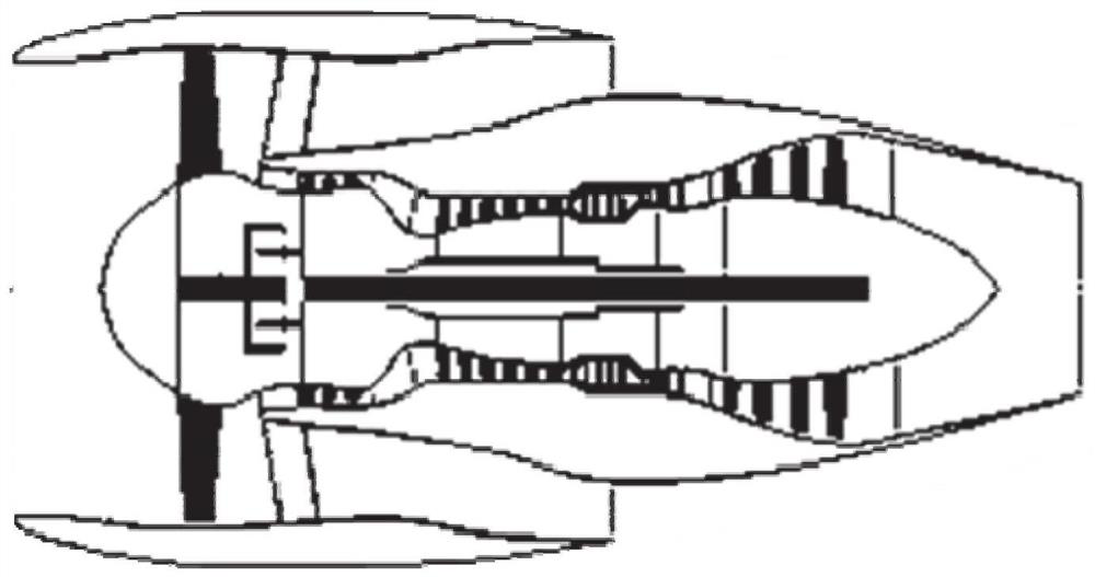
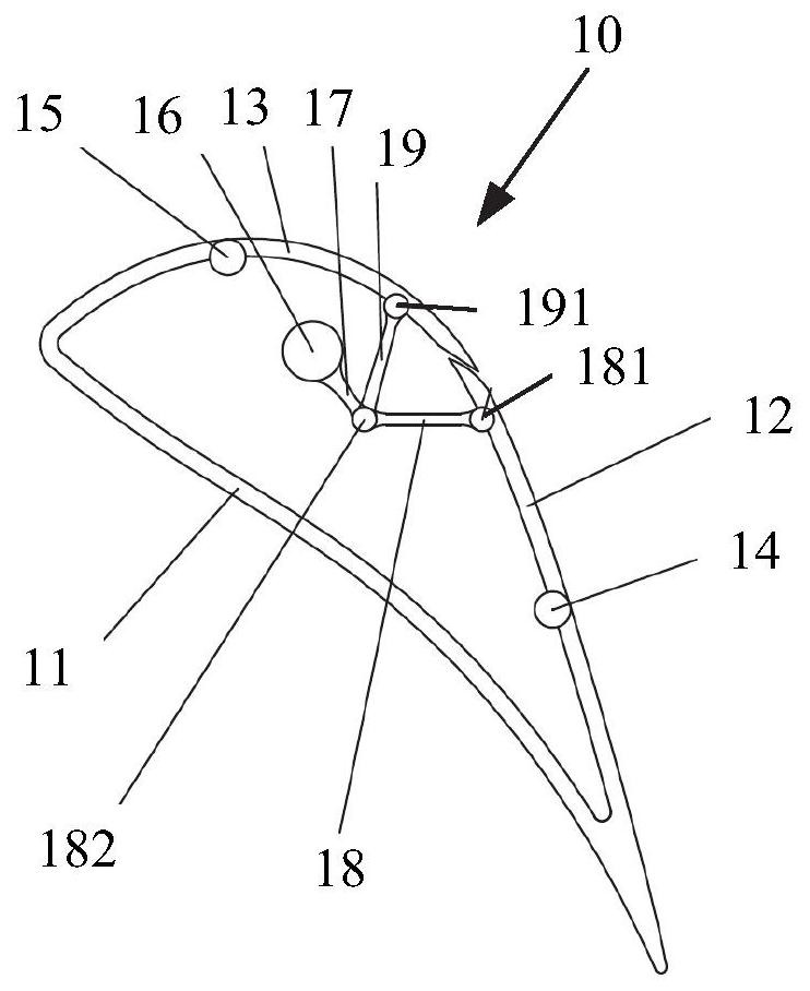
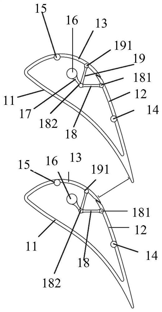
[0046] figure 1It is a structural schematic diagram of a dual-shaft direct-drive turbofan engine with a large bypass ratio in the prior art. figure 2 It is a structural schematic diagram of Embodiment 1 of the turbine guide vane in the variable cycle high bypass ratio turbofan engine of the present invention. image 3 It is a schematic diagram of the arrangement state of Embodiment 1 of the turbine guide vanes in the variable cycle large bypass ratio turbofan engine of the present invention Figure 1 . Figure 4 It is a schematic diagram of the arrangement state of Embodiment 1 of the turbine guide vanes in the variable cycle large bypass ratio turbofan engine of the present invention Figure II .

[0047] Such as Figure 1 to Figure 4 As shown, the variable cycle high bypass ratio turbofan engine of the present invention includes a plurality of turbine guide vanes 10, which include a blade portion 11 of a fixed structure, and a plurality of movable blade segments connect...

Embodiment 2

[0055] Figure 5 It is a structural schematic diagram of the second embodiment of the turbine guide vane in the variable cycle high bypass ratio turbofan engine of the present invention. Image 6 It is a schematic diagram of the arrangement state of the second embodiment of the turbine guide vanes in the variable cycle large bypass ratio turbofan engine of the present invention Figure 1 . Figure 7 It is a schematic diagram of the arrangement state of the second embodiment of the turbine guide vanes in the variable cycle large bypass ratio turbofan engine of the present invention Figure II .

[0056] Such as Figure 5 to Figure 7 As shown, the variable cycle high bypass ratio turbofan engine of the present invention includes a plurality of turbine guide vanes 20, which include a blade portion 21 of a fixed structure, and a plurality of movable blade segments connected by hinges , and form a hollow area with the blade part 21 of the fixed structure, and the throat area be...


PUM


Abstract

The present invention provides a turbofan engine with variable cycle and high bypass ratio, which comprises a plurality of turbine guide vanes, the turbine guide vanes include blade parts of a fixed structure, and a plurality of movable blade segments, and the plurality of movable blades The segment is connected by a hinge and forms a hollow area with the blade part of the fixed structure; by changing the movable blade segment to rotate to the inside or outside of the turbine guide vane, the distance between the two turbine guide vanes can be adjusted. Throat area. Under the condition of high bypass ratio, the invention reduces the flow area of ​​the guide vane of the turbine and changes the installation angle of the guide vane of the supercharging stage, which can achieve the effect of anti-breathing of the supercharging stage; avoids the energy loss caused by the deflation after the supercharging stage, Realize the all-envelope supercharging stage without blow-off; the connotation can pass through more air, which can provide a greater margin for the development of engine thrust.

Description

technical field [0001] The invention relates to the field of aero-engines, in particular to a variable-cycle turbofan engine with a large bypass ratio. Background technique [0002] figure 1 It is a structural schematic diagram of a dual-shaft direct-drive turbofan engine with a large bypass ratio in the prior art. Such as figure 1 As shown, a general dual-shaft direct-drive high bypass ratio turbofan engine will sequentially pass through the fan that initially compresses the airflow, the booster stage that further compresses the internal airflow, and the high-pressure compressor in order to heat the airflow according to the axial flow direction of the airflow. The combustion chamber, the high-pressure turbine and the low-pressure turbine that respectively drive the high-pressure compressor and the fan (including the booster stage), and the nozzle that allows the high-temperature and high-pressure air to be ejected at high speed. [0003] In order to improve the propulsio...

Claims


Application Information

Patent Timeline
Patent Type & Authority Patents(China)
IPC IPC(8): F01D9/04F01D17/16F02K3/075
CPCF01D9/041F01D17/16F02K3/075
Inventor 张宝严红明郑恒谭智勇
Owner AECC COMML AIRCRAFT ENGINE CO LTD
Why Eureka
Try Eureka