Process method of stamping forming of saw arm of swing saw

A stamping forming and process method technology, applied in the field of stamping process, can solve the problems of difficulty in improving the production efficiency of the swing saw saw arm, affecting the product quality, uneven force on the material plate, etc., so as to improve the forming quality, save the steps, reduce the Effects of Punch Time

Inactive Publication Date: 2019-04-09
HANGZHOU XIAOSHAN CHANGYU METAL MACHINERY
View PDF8 Cites 1 Cited by
  • Summary
  • Abstract
  • Description
  • Claims
  • Application Information

AI Technical Summary

Problems solved by technology

[0002] The saw arm of the swing saw is a board structure, as attached image 3 , attached Figure 4 As shown; in the conventional technology, it is generally made by stamping; but in the conventional technology, one piece is usually molded out, and the efficiency is not high; moreover, due to the structure of the swing saw arm, the middle hole area in the middle is larger, while the side The externally complete plate body, in the punching process, the material plate is not uniformly stressed, which can easily lead to local deformation and affect the product quality after punching
Existing continuous punching technologies, such as the technologies disclosed in the name of "Rubber Plug Continuous Punching Die" (publication number: CN104552462A) and "pumping plate type stator and rotor piece continuous punching die" (publication number: CN202984398U), are more suitable for products. rules, it is difficult to increase the productivity of the saw arm of the oscillating saw

Method used


Image

  • Process method of stamping forming of saw arm of swing saw
  • Process method of stamping forming of saw arm of swing saw
  • Process method of stamping forming of saw arm of swing saw

Examples


Embodiment

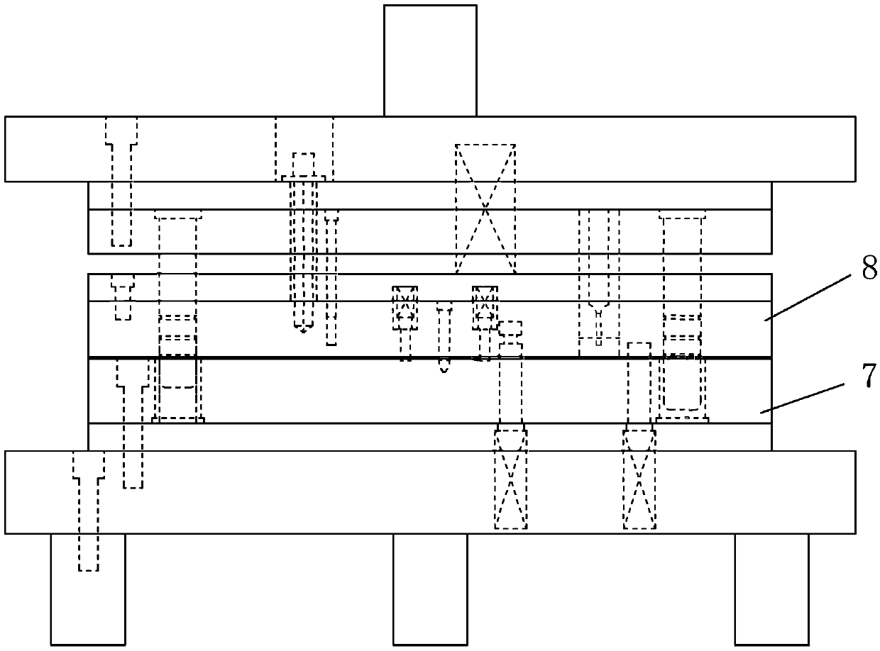
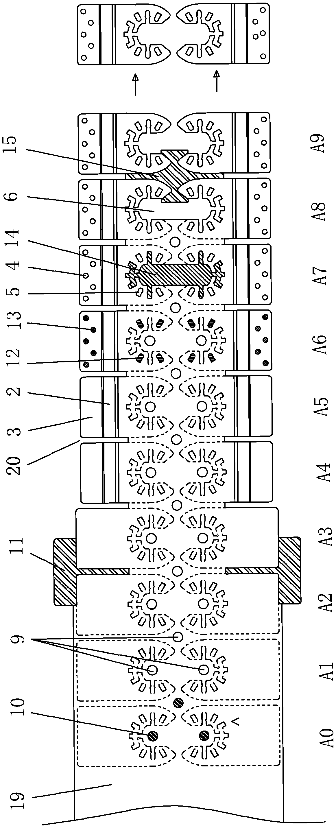
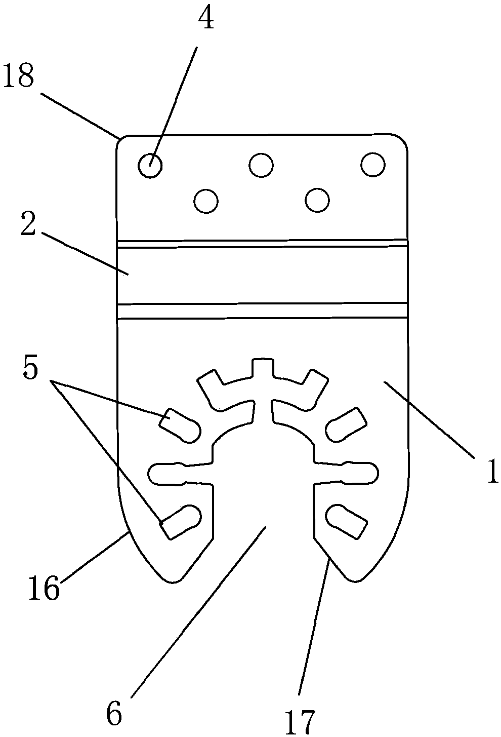
[0026] Embodiment: The present invention a kind of technology method of stamping and forming of saw arm of swing saw, its forming process, as attached figure 2 shown; the mold used, as attached figure 1 shown. The specific method is:

[0027] On the stamping position, the punched two swing saw arms are arranged symmetrically up and down, and the mouths of the middle holes 6 of the two swing saw arms face each other; A0 pre-carry and A1-A9 nine progressive positions are arranged in sequence in the mold cavity ,in:

[0028] 1) A0 pre-carry punching guide hole 9;

[0029] 2) An edge trimming punch 11 is set up and down between the A2 and A3 grades to cut off the side edge of the material plate 19 and form the top edge of the substrate 1, wherein the A2 grade punching cuts off the right part (here the right The side part refers to the right side of the two-piece oscillating saw arm at the level of progress, not the right side of the finished product of the single-piece oscil...


PUM


Abstract

The invention relates to a process method of stamping forming of a saw arm of a swing saw. the method comprises the steps that opening parts of middle holes of opening parts of two swing saw arm middle holes are opposite; an A0 pre-entering position and A1 to A9 grading positions are arranged in a mold cavity in sequence; firstly the A0 pre-entering position is used for stamping a guide hole; secondly, on the A2 grading position and the A3 grading position, the board side is cut off, and a top side of a base plate is formed, the A2 grading position punches and cuts off the right side part, theA3 grading position punches and cuts off the left part, the A2 grading position and the A3 grading position cut out the side upper edge connected with the top side, and an upper middle groove and a lower middle groove are formed in a board; 3, the A4 grading position bends the inclined part and a front end flat plate; 4, the A6 grading position punches the convex point of the middle and an inclined hole in the outer side at the same time; 5, the A7 grading position punches a middle hole; 6, the A8 grading position and the A9 grading position enable a punching part of the A9 grading position to be broken away from a board (19), and the two swing saw arms are broken, so that an outer lip side and an inner lip side are formed, wherein the A8 grading position forms the outer lip side and theinner lip side on the right side, and the A9 grading position forms an outer lip side and an inner lip side on the left side.

Description

technical field [0001] The invention relates to a stamping process, in particular to a process method for stamping the saw arm of an oscillating saw. Background technique [0002] The saw arm of the swing saw is a board structure, as attached image 3 , attached Figure 4 As shown; in the conventional technology, it is generally made by stamping; but in the conventional technology, one piece is usually molded out, and the efficiency is not high; moreover, due to the structure of the swing saw arm, the middle hole area in the middle is larger, while the side During the stamping process, the plate body with a complete exterior is unevenly stressed, which can easily lead to local deformation and affect the quality of the product after stamping. Existing continuous punching technologies, such as the technologies disclosed in the name of "Rubber Plug Continuous Punching Die" (publication number: CN104552462A) and "pumping plate type stator and rotor piece continuous punching die...

Claims


Application Information

Patent Timeline
Patent Type & Authority Applications(China)
IPC IPC(8): B21D37/08B21D35/00B21D28/34B21D28/14B21D7/08
CPCB21D7/08B21D28/14B21D28/34B21D35/002B21D37/08
Inventor 闻立昌
Owner HANGZHOU XIAOSHAN CHANGYU METAL MACHINERY
Why Eureka
Try Eureka