
Multi-group contact electromagnetic relay with impact resistance and fall resistance

An electromagnetic relay, anti-shock technology, applied in the direction of electromagnetic relay, electromagnetic relay details, relay, etc., can solve the problems of relay function failure, detachment, etc., to increase creepage distance, increase creepage distance, reduce range size Effect

Pending Publication Date: 2019-04-05
ZHANGZHOU HONGFA ELECTROACOUSTIC CO LTD
View PDF0 Cites 1 Cited by
  • Summary
  • Abstract
  • Description
  • Claims
  • Application Information

AI Technical Summary

Benefits of technology

The present in this patented technology improves upon existing methods for prevention or reduction of damage caused during transportation due to vibrations and shocks experienced while shipping products over long distances. It involves adding a new component called a restorreed back onto the pushcard's surface instead of directly attaching it to its own movement/static springs. By connecting these parts at right angles, they create space inside them without interferring each others. These technical improvements improve the overall performance and durability of the pushCard design compared to previous designs.

Problems solved by technology

This patented technical problem addressed in this patents describes how an electricity-based device can have its own mechanism where there may come into play when subjecting them during shipping due to factors like weight distribution, bouncing movements, temperature changes, etc., resulting in failure of the switch's operation.

Method used


Image

  • Multi-group contact electromagnetic relay with impact resistance and fall resistance
  • Multi-group contact electromagnetic relay with impact resistance and fall resistance
  • Multi-group contact electromagnetic relay with impact resistance and fall resistance

Examples


Embodiment

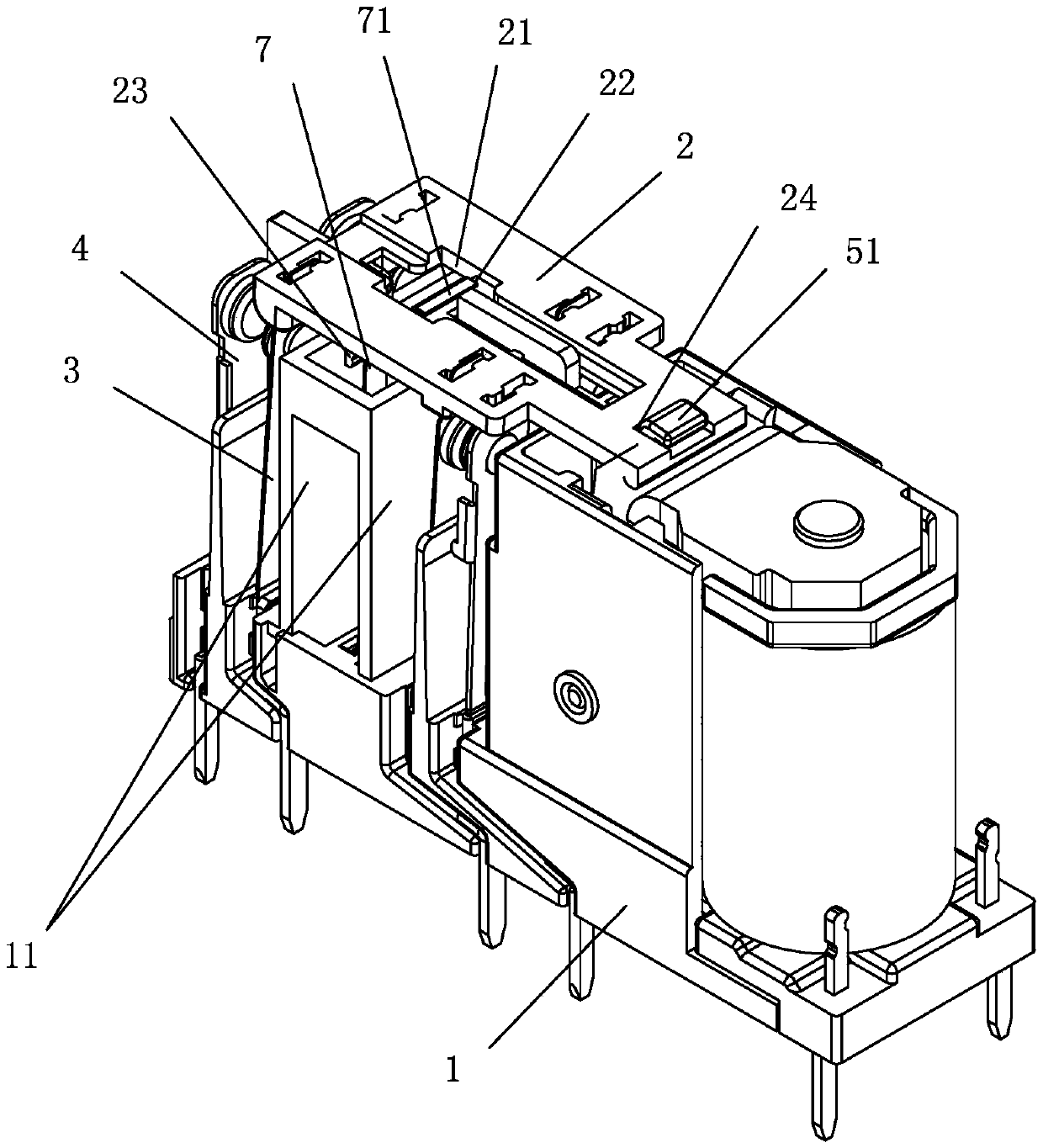
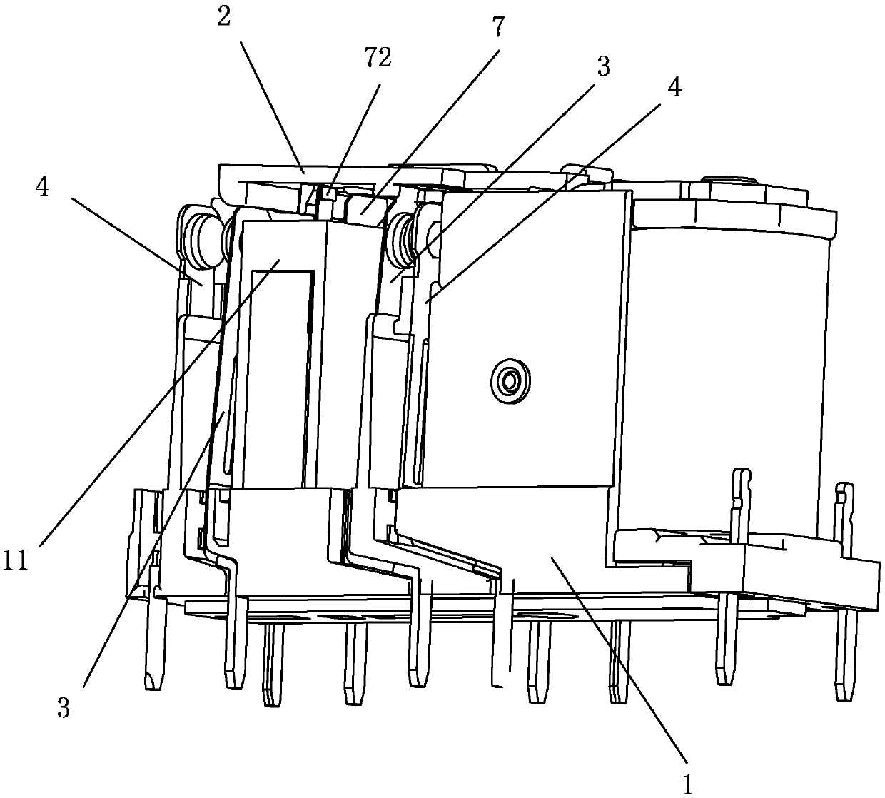
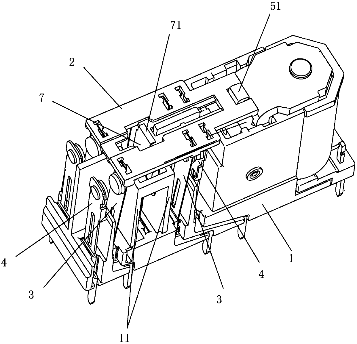
[0031] see Figure 1 to Figure 14 As shown, a shock-resistant and drop-resistant multi-group contact electromagnetic relay of the present invention includes a base 1, a push card 2, a magnetic circuit part and a contact part; the magnetic circuit part and the contact part are respectively installed On the base 1, the housing 6 is fixed on the base 1 and accommodates the magnetic circuit part and the contact part; the contact part includes multiple sets of moving spring parts 3 and static spring parts 4 that match, wherein, The moving spring part 3 includes a moving reed 31, a moving contact 32 and a moving spring lead-out piece 33, and the static spring part 4 includes a static reed 41 and a static contact 42; The other end of the push card 2 is connected to each moving spring part 3 of the magnetic circuit part, specifically the moving reed 31 connected to the moving spring part 3; the other end of the push card 2 is also connected to A recovery reed 7, the bottom end of the...


PUM


Abstract

The invention discloses a multi-group contact electromagnetic relay with impact resistance and fall resistance. The multi-group contact electromagnetic relay comprises a base, a push board, a magneticcircuit part and a contact part, wherein the magnetic circuit part and the contact part are mounted on the base; the contact part comprises a plurality of groups of matched moving reed parts and static reed parts; one end of the push board is engaged with the armature part of the magnetic circuit part; the other end of the push board is connected to each moving reed part of the magnetic circuit part, and is further connected with a return reed; the bottom of the return reed is connected with the base; the push board is provided with a first bayonet penetrating in the thickness direction; thetop of the return reed matches the first bayonet of the push board; and a first stopping mechanism and a second stopping mechanism are further arranged between the return reed and the push board. Thepush board cannot be detached from the return reed and the armature cooperating with the push board under the effect of severe impact after the relay is assembled. The relay has good impact resistanceand fall resistance.

Description


Claims


Application Information

Patent Timeline
Owner ZHANGZHOU HONGFA ELECTROACOUSTIC CO LTD
Learn More