
Laser echo processing method and system with adaptive automatic gain control

A technology of automatic gain control and laser echo, which is applied in the field of geographic surveying and mapping, can solve the problems of oversaturation of the amplifier circuit, large range of echo amplitude variation, and failure to collect echo signals, etc., to maximize the signal-to-noise ratio and improve performance , the effect of improving the quality

Inactive Publication Date: 2019-04-05
深圳天眼激光科技有限公司 +1
View PDF6 Cites 6 Cited by
  • Summary
  • Abstract
  • Description
  • Claims
  • Application Information

AI Technical Summary

Problems solved by technology

[0004] The actual application environment of laser ranging is more complex, affected by various factors such as laser emission energy, measurement distance, surface object reflectivity and atmospheric transmittance, the echo amplitude varies widely, which may cause the amplifier circuit to oversaturation, It is impossible to realize multi-echo measurement, and even lead to no echo signal at all in the subsequent stage; the traditional automatic gain control method is used to fix the light output energy of the laser, and only adjust and control the amplification factor of the automatic gain amplifier according to the echo amplitude. It is very good to control the echo amplitude in an appropriate range, and the signal-to-noise ratio of the echo signal is not high

Method used


Image

  • Laser echo processing method and system with adaptive automatic gain control
  • Laser echo processing method and system with adaptive automatic gain control
  • Laser echo processing method and system with adaptive automatic gain control

Examples


Embodiment 1

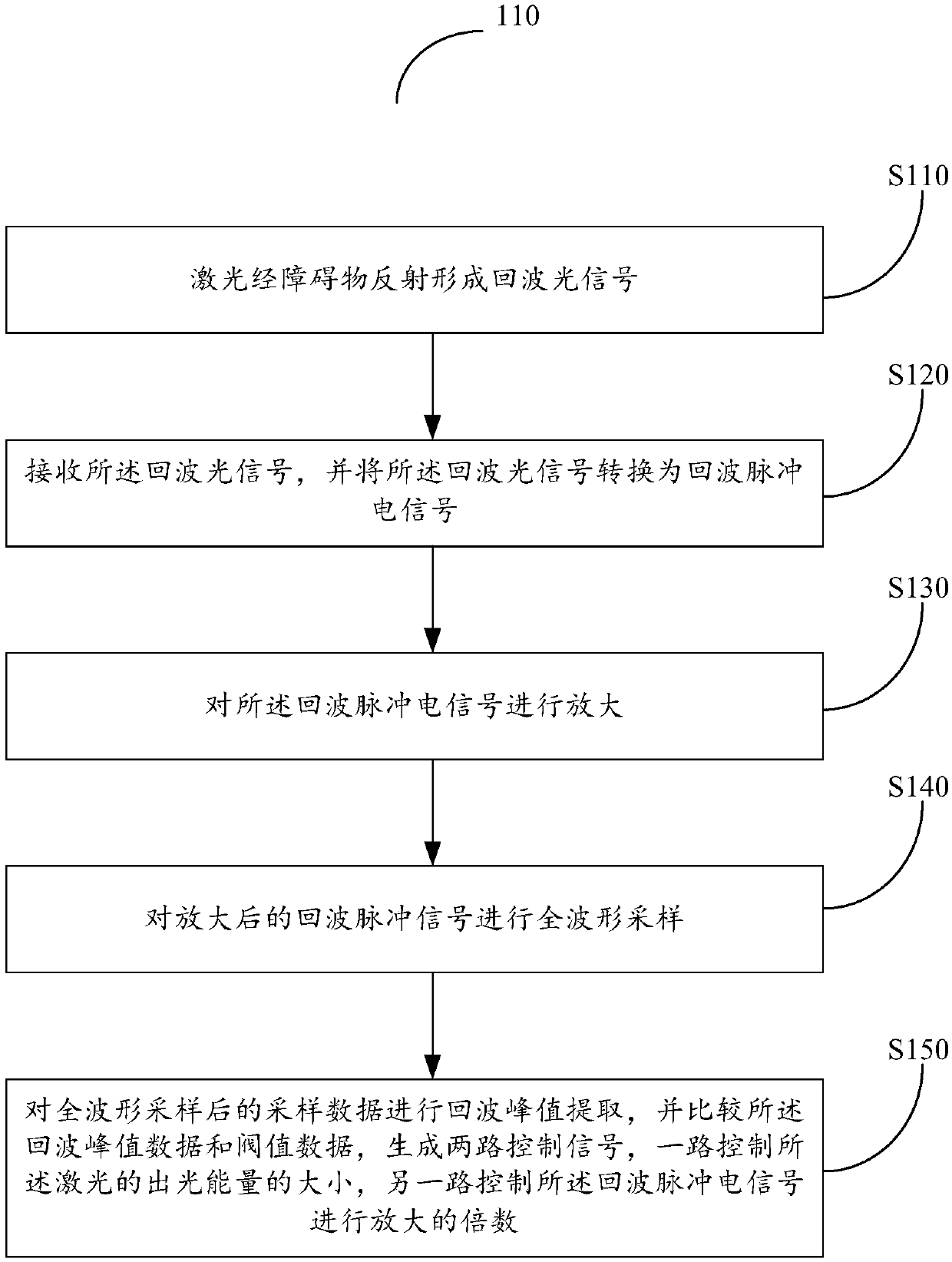
[0033] see figure 1 , is a flow chart of the steps of the adaptive automatic gain control laser echo processing method 100 provided in Embodiment 1 of the present invention, including the following steps:

[0034] Step S110: the laser beam is reflected by the obstacle to form an echo optical signal.

[0035] Step S120: receiving the echo optical signal, and converting the echo optical signal into an echo pulse electrical signal;

[0036] Step S130: amplifying the echo pulse electric signal;

[0037] Step S140: Sampling the full waveform of the amplified echo pulse signal;

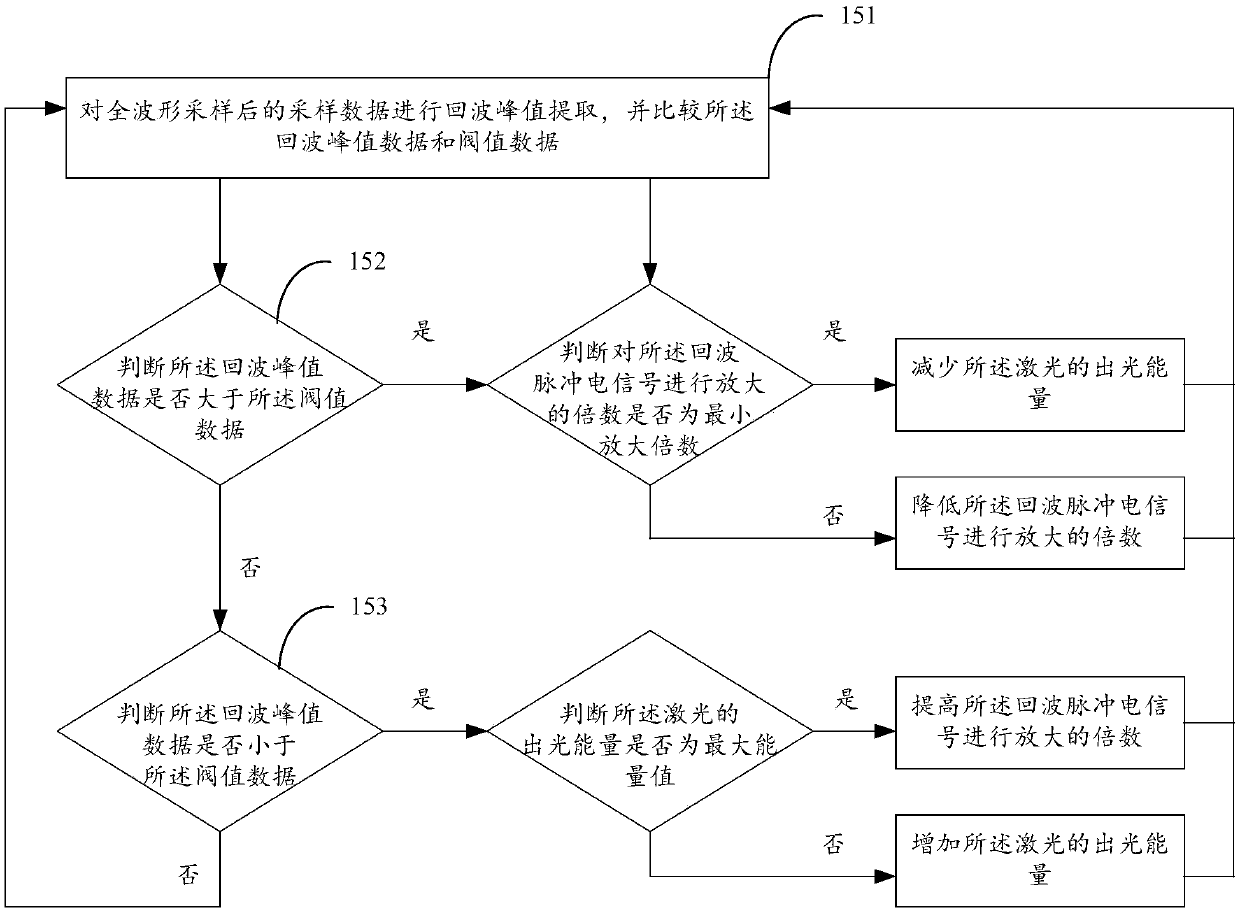
[0038] Step S150: Perform echo peak extraction on the sampled data after full waveform sampling, and compare the echo peak data with the threshold data to generate two control signals, one of which controls the light output energy of the laser, and the other controls The echo pulse electrical signal is amplified.

[0039] In step S150, when the echo peak data is greater than the upper limit of the thres...

Embodiment 2

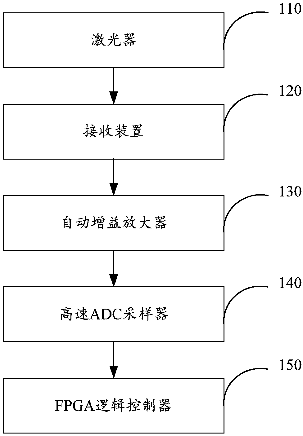
[0047] image 3 A schematic structural diagram of the laser echo processing system for adaptive automatic gain control provided by the present invention, including:

[0048] a laser 110, configured to emit laser light, and the laser light is reflected by an obstacle to form an echo optical signal;

[0049] The receiving device 120 is configured to receive the echo optical signal, and convert the echo optical signal into an echo pulse electrical signal;

[0050] an automatic gain amplifier 130, configured to amplify the echo pulse electrical signal;

[0051] A high-speed ADC sampler 140 is used to sample the full waveform of the amplified echo pulse signal;

[0052] The FPGA logic controller 150 is used to extract the echo peak value from the sampled data after full waveform sampling, and compare the echo peak value data with the threshold data to generate two control signals, one for controlling the output energy of the laser. The other way controls the amplification factor...


PUM


Abstract

The invention provides a laser echo processing method and system. The method comprises the following steps of: reflecting a laser beam by an obstacle to form an echo optical signal; converting the echo optical signal into an echo pulse electric signal; amplifying the echo pulse electric signal and carrying out full-waveform sampling; and carrying out echo peak extraction on the sampling data afterthe full-waveform sampling, and comparing echo peak data and threshold data to generate two paths of control signals, wherein one path controls light emitting energy of the laser beam and the other path controls an amplification factor of the echo pulse electric signal. When the echo peak data is larger than a threshold data upper limit value, the light emitting energy of the laser beam or the amplification factor of the echo pulse electric signal is reduced; when the echo peak data is smaller than a threshold data lower limit value, the light emitting energy of the laser beam or the amplification factor of the echo pulse electric signal is increased. Therefore, the amplitude of the echo signals is more stable while the signal to noise ratio of the echo signals is maximized, the quality of the echo signals is improved, and the laser ranging performance is improved.

Description

technical field [0001] The invention relates to the technical field of geographic surveying and mapping, in particular to a laser echo processing method with adaptive automatic gain control. Background technique [0002] With the rapid development of high and new technologies such as electronic technology, laser technology, and optical technology, it provides an important foundation for the improvement of long-range range finders. In particular, emerging disciplines represented by laser applications are on the rise. The innovation of related concepts and rich practical experience have provided effective references for the research work of long-range laser ranging technology. [0003] The principle of laser ranging is to calculate the product of the laser flight time interval and the speed of light. The speed of light is a known condition, which is 300,000 km / s, and what needs to be measured is the laser flight time interval. The laser flight time interval refers to the tim...

Claims


Application Information

Patent Timeline
Patent Type & Authority Applications(China)
IPC IPC(8): G01S17/89
CPCG01S17/89
Inventor 虞静唐海龙黄仁兵黄贵余刘文潘文武唐丹孔琪
Owner 深圳天眼激光科技有限公司
Learn More