


Quick Research
Generate reliable direction feasibility study reports for your R&D in just a few steps.

Technical Q&A
Discover and master advanced knowledge NOW. Basics, ideas, possibilities, all at once.

Find Solutions
As an expert in R&D theories, this can generate solutions to your technical problems instantly.

Evaluate Feasibility
Analyze your overall solution with one click, know your potential R&D risks in advance.

Monitor Landscape
Get weekly tech updates, stay abreast of the latest tech innovations and key insights.
Valve rocker chamber with composite lubrication oil path, and cylinder head cover
A valve rocker arm, cylinder head cover technology, applied in the direction of cylinder head, valve accessories lubrication, cylinder, etc., can solve the problem of insufficient lubrication of the friction pair of the rocker arm, avoid failure to work, reduce parts wear, and ensure normal operation. Effect
- Summary
- Abstract
- Description
- Claims
- Application Information
AI Technical Summary
Problems solved by technology
Method used
Image

Examples
Embodiment 1
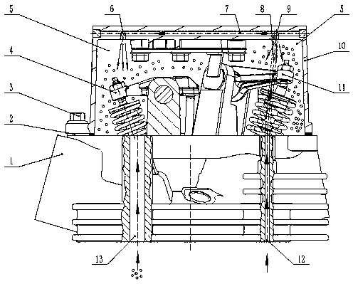
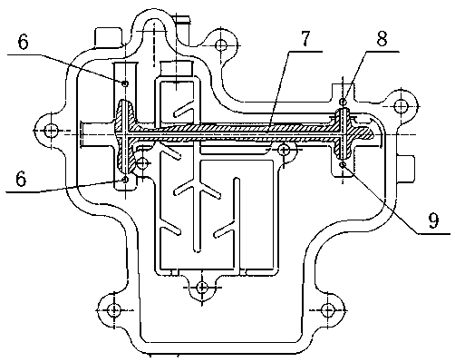
[0025] Such as figure 1 As shown, this embodiment provides a valve rocker arm chamber 5 with a composite lubricating oil circuit. The valve rocker arm chamber 5 is formed by closing the cylinder head 1 and the cylinder head cover 10, and includes an intake rocker arm assembly 4. Exhaust lubrication components. The size of the cylinder head 1 is adapted to the size of the cylinder head cover 10 . by figure 1 The direction shown in the figure shall prevail. There is a cylinder head oil mist channel 13 and a cylinder head lubricating oil channel 12 on the left and right sides of the cylinder head 1 respectively. The cylinder head oil mist channel 13 and the cylinder head lubricating oil channel 12 are both vertical. It is arranged and connected up and down so that the valve rocker chamber 5 communicates with the oil passage on the cylinder block and the crankcase. The lower opening of the cylinder head oil mist passage 13 communicates with the oil mist passage on the crankcase...
Embodiment 2
[0036]The difference between this embodiment and Embodiment 1 is that there is only one cylinder head lubricating oil passage 12 in this embodiment, but there are two oil mist lubricating oil passages in the cylinder head 1, both of which are located in the intake rocker arm assembly. 4 are located on one side, and one front and one back are set.
[0037] The oil mist lubrication process and the forced lubrication process in this embodiment are basically the same as those in Embodiment 1, and will not be repeated here.
Embodiment 3
[0039] The difference between this embodiment and Embodiment 1 is that in this embodiment, there are two lubricating oil passages in the cylinder head cover 10, but there is only one oil mist lubricating oil passage in the cylinder head 1, and one of the cylinder head lubricating oil passages 12 is arranged on the side where the exhaust rocker arm assembly 11 is located, and the other lubricating oil channel of the cylinder head cover 10 and the oil mist lubricating oil channel of the cylinder head 1 are arranged on the side where the intake rocker arm is located. Moreover, one cylinder head cover 10 lubricating oil passage is arranged in the cylinder rocker chamber, while the other cylinder head lubricating oil passage 12 is arranged in the cylinder head 1 on or near the side wall of the cylinder head cover 10 . In order to correspond to another cylinder head lubricating oil passage 12, the cylinder head cover lubricating oil passage a8 can be added one above the position of ...
PUM
 Abstract
Description
Claims
Application Information
 - R&D Engineer
- R&D Manager
- IP Professional
- Industry Leading Data Capabilities
- Powerful AI technology
- Patent DNA Extraction
Browse by: Latest US Patents, China's latest patents, Technical Efficacy Thesaurus, Application Domain, Technology Topic, Popular Technical Reports.
© 2024 PatSnap. All rights reserved.Legal|Privacy policy|Modern Slavery Act Transparency Statement|Sitemap|About US| Contact US: help@patsnap.com