
Automobile anti-lock failure remedy switch

An anti-lock and anti-lock braking technology, applied in the field of automobile brake devices, can solve problems such as failure of the anti-lock braking system, and achieve the effects of avoiding wheel locking, increasing service life and reducing damage

Inactive Publication Date: 2019-04-05
象山权友机械有限公司
View PDF0 Cites 0 Cited by
  • Summary
  • Abstract
  • Description
  • Claims
  • Application Information

AI Technical Summary

Problems solved by technology

[0004] The purpose of the present invention is to provide a remedial switch for automobile anti-lock brake failure, which overcomes the problem of failure of the anti-lock brake system caused by circuit failure

Method used


Image

  • Automobile anti-lock failure remedy switch
  • Automobile anti-lock failure remedy switch
  • Automobile anti-lock failure remedy switch

Examples


Embodiment 1

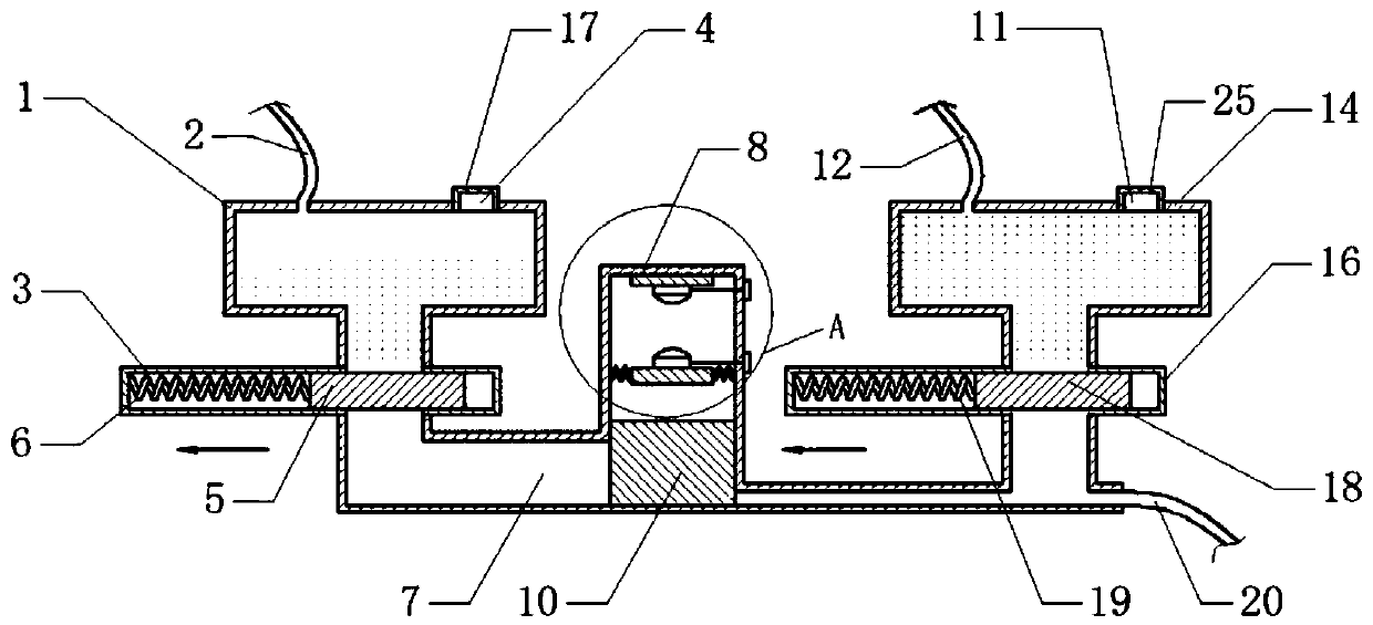
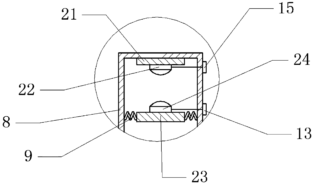
[0022] Embodiment one is basically as attached figure 1 And attached figure 2 As shown, the automobile anti-lock brake failure remedial switch includes the anti-lock brake system installed in the car, the first water outlet mechanism, the switch contact device, the second water outlet mechanism, the first water collection tank and the second water collection tank for collecting rainwater The first water outlet mechanism includes a first water storage tank 1 installed on the car. The first water storage tank 1 communicates with a first water collection pipe 2 whose upper opening is located in the first water collection tank. The top of the first water storage tank 1 is provided with a first The first water inlet 4 and the first water inlet 4 are threadedly connected with the first water filling cap 17, the bottom of the first water storage tank 1 is connected with the pipeline 7, and the first chute 3 is arranged in the pipeline 7, and the sliding connection in the first chute...

Embodiment 2

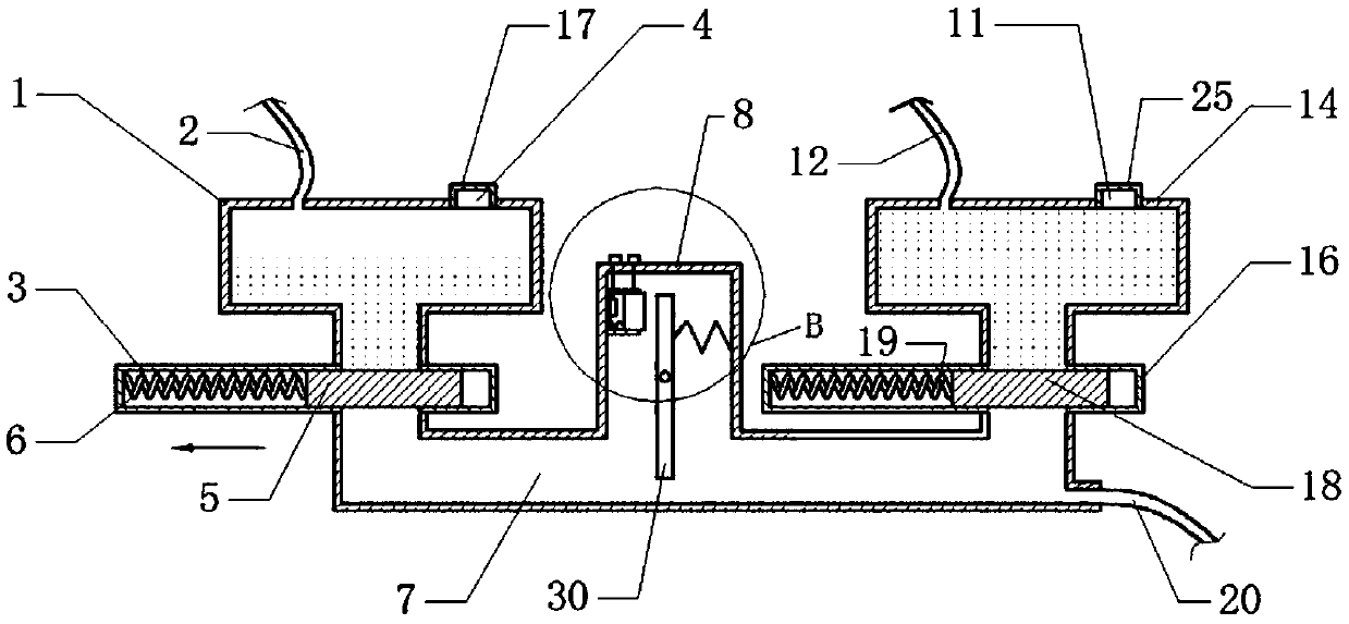
[0027] Embodiment two as attached image 3 And attached Figure 4 As shown, the difference from Embodiment 1 is that the switch contact device includes a box body 8, the box body 8 communicates with the pipeline 7, the pipeline 7 is connected with a water outlet pipe 20, and the outlet of the water outlet pipe 20 is located above the brake disc, and the side of the box body 8 The wall is fixedly connected with a cylinder 26, the bottom of the cylinder 26 is fixedly connected with a conductive static contact block 27, and the inside of the cylinder 26 is slidably connected with a conductive dynamic contact block 28, and the dynamic contact block 28 and the cylinder 26 A third spring 29 is fixedly connected between them, and a lever 30 is provided on one side of the opening of the cylinder 26. The middle part of the lever 30 is hinged with the box body 8, and a fourth spring 31 is fixedly connected between the lever 30 and the box body 8, and the box body The outer wall of 8 is p...


PUM


Abstract

The invention relates to the field of automobile braking devices and discloses an automobile anti-lock failure remedy switch. The automobile anti-lock failure remedy switch comprises an anti-lock system, a first water outlet mechanism and a switch contact device which are arranged in an automobile; the first water outlet mechanism comprises a first water storage tank mounted on the automobile; a pipeline communicates with the bottom of the first water storage tank; a water outlet pipe communicates with the pipeline; an outlet of the water outlet pipe is formed above a brake disc; a first slidegroove is formed in the pipeline; a first slide block used for blocking the first water storage tank is slidingly connected to the interior of the first slide groove; a first spring is connected between the first slide block and the internal wall of the first slide groove; the switch contact device comprises a box body; the box body communicates with the pipeline; and a switching mechanism used for switching on a circuit of an anti-lock system is arranged at the top of the box body. The automobile anti-lock failure remedy switch has the advantage that the circuit of an anti-lock braking system is switched on so as to avoid wheel locking when the circuit of the anti-lock braking system has a fault.

Description

technical field [0001] The invention relates to the field of automobile brake devices, in particular to an automobile anti-lock brake failure remedial switch. Background technique [0002] Locking refers to the state in which the tires no longer rotate due to a brake during the braking process of the car. The anti-lock braking system is a kind of vehicle safety control system that uses intermittent braking to prevent the wheels from locking up. The working principle of the anti-lock braking system is to quickly judge the locked state of the wheel according to the speed signal from the speed sensor on each wheel when the car is braking, so as to increase or decrease the braking force to keep the wheel scroll. At present, anti-lock braking system has been used as the standard configuration of the car. [0003] However, in actual application, the anti-lock braking system may cause a circuit failure due to various reasons, so that the anti-lock braking system cannot receive t...

Claims


Application Information

Patent Timeline
IPC IPC(8): B60T8/88
CPCB60T8/88
Inventor 孙友权
Owner 象山权友机械有限公司
Learn More