Machine tool

A technology of machine tools and motors, applied in the field of machine tools, can solve the problems of decreased productivity, complex operations, time required for testing, etc., and achieve the effect of preventing unwanted movement and improving productivity

Active Publication Date: 2019-04-05
BROTHER KOGYO KK
View PDF9 Cites 0 Cited by
  • Summary
  • Abstract
  • Description
  • Claims
  • Application Information

AI Technical Summary

Problems solved by technology

Machine tools have multiple gravity axes, so it is necessary to determine whether the brake is malfunctioning for each gravity axis, and there are problems such as complicated work, time required for testing, and decreased productivity

Method used


Image

  • Machine tool
  • Machine tool
  • Machine tool

Examples


Embodiment Construction

[0024] Hereinafter, the present invention will be described in detail based on drawings showing machine tools of the embodiments. In the following description, up and down, left and right, and front and rear indicated by arrows in the drawings are used.

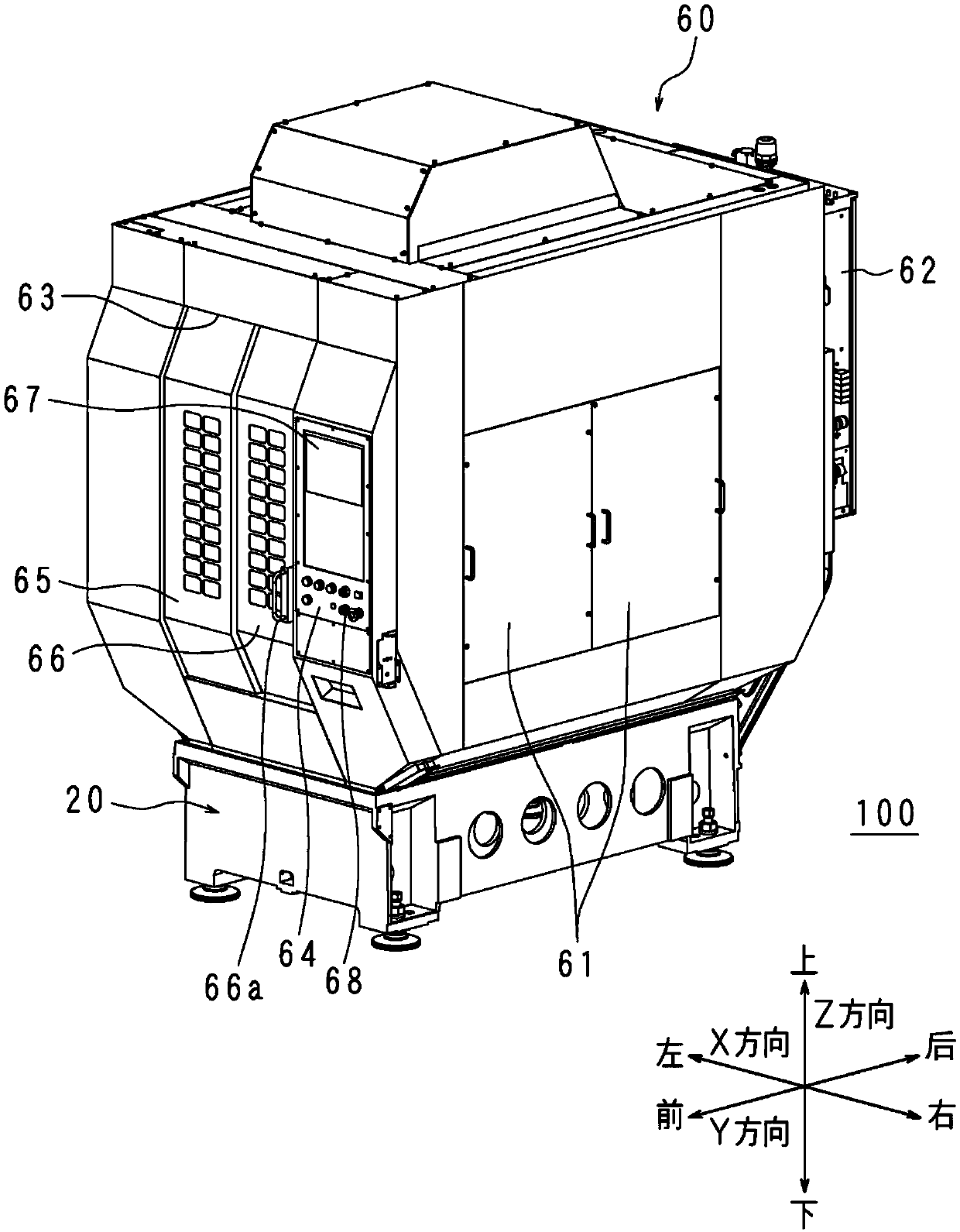
[0025] Such as figure 1 As shown, the machine tool cover 60 is provided on the upper side of the base 20 of the machine tool 100 . The machine tool cover 60 has a rectangular box shape. The machine tool cover 60 has two detachable plates 61 at the center of both left and right sides. The operator removes the plate 61 as necessary to perform maintenance and management of the machine tool. The control panel 62 is provided on the back of the machine tool cover 60 and has a control unit 90 for controlling the operation of the machine tool and an amplifier for supplying electric power to each motor.

[0026] A vertically elongated rectangular opening 63 is provided at the front central portion of the machine tool cover 60 , an...


PUM


Abstract

The present invention provides a machine tool capable of efficiently determining a failure of a brake and having excellent workability and productivity. The machine tool has a motor that drives two ormore members and has a brake, a working portion that operates the brakes of the motors; a load imparting portion which applies load to the motor under the situation that the working portion enables the brake to work; a determination unit determines whether or not the brake of each of the motors is faulty based on the amount of movement of each of the motors when the load is applied by the load applying unit; and a first moving unit, which causes at least one member to move toward to the two or more members at positions that do not interfere with each other under driving.

Description

technical field [0001] The invention relates to a machine tool with a motor with a brake. Background technique [0002] The machine tool sequentially replaces the tools attached to the spindle to perform milling, tapping, and other processing. The machine tool has a support table (base), a spindle head, a column, and a tool magazine. The column is arranged on the upper part of the abutment near the rear. The spindle head moves in the Z-axis direction along the front surface of the column using a Z-axis motor. The spindle head internally supports the spindle in a rotatable manner. The spindle is rotated by a spindle motor. The tool magazine has a chain that revolves along the track driven by the tool magazine motor. The chain has a plurality of holding arms. Each grip arm holds the tool in a detachable manner. After processing, the spindle head is raised, and the tool mounted on the spindle is held by the holding arm. The magazine motor rotates the chain to move the h...

Claims


Application Information

Patent Timeline
Patent Type & Authority Applications(China)
IPC IPC(8): B23Q3/155B23Q17/00
CPCB23Q3/1552B23Q17/00
Inventor 堀冈大士入江武志
Owner BROTHER KOGYO KK
Why Eureka
Try Eureka