
HC six-roller mill middle roller body end chamfer grinding method

A six-high rolling mill and intermediate roll technology, which is applied in the field of chamfering and grinding the end of the intermediate roll of the HC six-high rolling mill, can solve problems such as peeling of the end of the intermediate roll body, economic impact on safety, and scrapping of the intermediate roll. Achieve the effects of reducing abnormal loss, solving end ring cracks and peeling, and avoiding stress concentration

Active Publication Date: 2019-04-02
BAOSTEEL ROLL SCI & TECH
View PDF8 Cites 2 Cited by
  • Summary
  • Abstract
  • Description
  • Claims
  • Application Information

AI Technical Summary

Problems solved by technology

However, if the edge of the middle roll body bears a large contact stress, it will cause peeling or ring cracking at the end of the middle roll body
Premature peeling or ring cracking of the intermediate roll will not only easily cause rolling accidents, but also lead to the direct scrapping of the intermediate roll, which will have adverse effects on both safety and economy

Method used


Image

  • HC six-roller mill middle roller body end chamfer grinding method
  • HC six-roller mill middle roller body end chamfer grinding method

Examples


Embodiment 1)

[0014] The chamfering grinding method of the end of the middle roll body of the HC six-high rolling mill of the present embodiment is as follows:

[0015] ① The chamfering structure design of the end of the roller body.

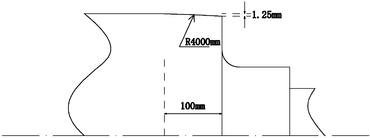
[0016] see figure 1 , In this embodiment, the chamfering structure of the middle roll body of the HC six-high rolling mill is designed to be R4000mm×100mm, and the unilateral drop is 1.25mm.

[0017] ②Chamfer grinding process at the end of the roller body.

[0018] Grinding is performed directly on the HERKULES CNC grinding machine. In the grinding parameter input column, input the grinding radius R4000mm, and set the width to 100mm. In this way, a grinding curve is output, and the built-in system grinds according to this curve.

[0019] According to the normal grinding feed amount and retraction amount of the roll body, each pass of grinding is carried out, and the chamfering angle difference at the end of the roll body is finally controlled to 1.25mm.

...

Embodiment 2)

[0024] The chamfering grinding method of the end of the middle roll body of the HC six-high rolling mill of the present embodiment is as follows:

[0025] ① The chamfering structure design of the end of the roller body.

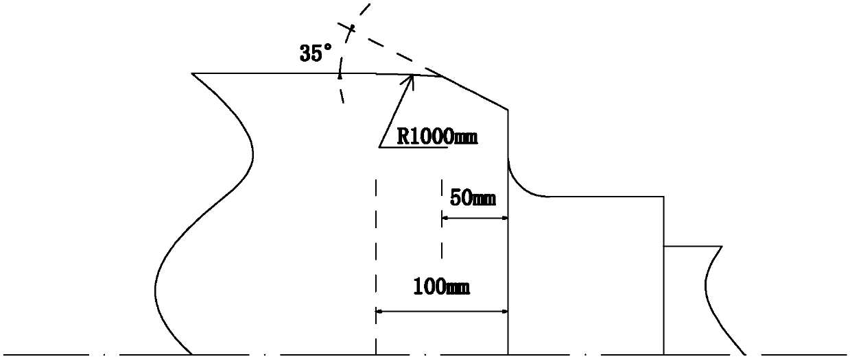
[0026] see figure 2 In this embodiment, the chamfering structure at the end of the middle roll body of the HC six-high rolling mill is designed to be 35°×50mm+R1000mm×50mm.

[0027] ②Chamfer grinding process at the end of the roller body.

[0028] First, the end of the roll body is turned into a chamfer structure of 35°×50mm, and then it is ground on a HERKULES CNC grinding machine, and the grinding radius R1000mm is input in the grinding parameter input column, and the width is set to 50mm, so that a grinding line is output Grinding curve, the self-contained system will grind according to the curve.

[0029] The specific grinding parameters are also shown in Table 1.


PUM


Abstract

The invention discloses an HC six-roller mill middle roller body end chamfer grinding method. The method comprises roller body end chamfer structural design and a roller body end chamfer grinding process. In the roller body end chamfer structural design, a roller body end chamfer is designed to be R (3000-5000mm)*(80-120mm), and the unilateral drop is 1-1.5mm; or the roller body end chamfer is designed to be (20-50 degrees)*(30-70mm)+R(800-1200mm)*(30-70mm). In the grinding method, by optimally designing the HC six-roller mill middle roller body end chamfer structure and developing the grinding process matched with the structure, the problem of stress concentration produced by extrusion of a high-hardness working roller on the edge of a low-hardness middle roller can be avoided, therefore,the invalidation problems such as end ring cracking and stripping caused by the fact that the middle roller bears contact fatigue stress in the using process are solved, and abnormal loss of the middle roller is reduced.

Description

technical field [0001] The invention belongs to the technical field of intermediate rolls of HC six-high rolling mills, and in particular relates to a method for chamfering and grinding the ends of intermediate rolls of HC six-high rolling mills. Background technique [0002] The HC six-high mill mainly realizes the control of the strip shape through work roll bending / transverse roll shifting of intermediate rolls, work roll bending, and intermediate roll bending. Roll bending and roll shifting technology can well solve the problem of shape quality control, but it is followed by high requirements on the overall performance of the roll. [0003] Since the contact stress distribution state between the rolls is always in a dynamic process, and the hardness of the intermediate roll is lower than that of the work roll, it will be pressed by the high-hardness work roll during the rolling process, resulting in contact fatigue and stress concentration. However, if the edge of the m...

Claims


Application Information

Patent Timeline
Patent Type & Authority Applications(China)
IPC IPC(8): B24B1/00
CPCB24B1/00
Inventor 陈伟王辉谢晶胡现龙刘洋兰勇乔建平卢守栋
Owner BAOSTEEL ROLL SCI & TECH
Learn More