A universal fixture for self-adaptive clamping of blade tip or blade crown process table

A self-adaptive, process table technology, used in manufacturing tools, workpiece clamping devices, clamping and other directions, can solve the problems of large clamping stress of parts, unqualified top holes, deformation of parts, etc., to reduce clamping stress, reduce Deformation and versatility

Active Publication Date: 2020-10-30
AECC AERO SCI & TECH CO LTD
View PDF5 Cites 0 Cited by
  • Summary
  • Abstract
  • Description
  • Claims
  • Application Information

AI Technical Summary

Problems solved by technology

[0002] At present, the blade tip fixtures for blade profile processing all use the method of positioning and clamping the top hole of single-drive equipment or the positioning and clamping of the top hole of double-drive equipment. There are two following disadvantages in this method: 1. The tightness will lead to a large clamping stress of the part during the processing process, which will lead to the stress release and deformation of the part after the processing is completed; 2. Regardless of single drive or double drive, the center hole is used for positioning, the size and position of the center hole determine the The qualified rate of blade profile processing, however, there will be deformation after rough machining and heat treatment of most parts, resulting in unqualified tip holes

Method used


Image

  • A universal fixture for self-adaptive clamping of blade tip or blade crown process table
  • A universal fixture for self-adaptive clamping of blade tip or blade crown process table
  • A universal fixture for self-adaptive clamping of blade tip or blade crown process table

Examples


Embodiment Construction

[0050] In order to make the purpose, technical solution and advantages of the present invention clearer, the technical solution of the present invention will be described in detail below. Apparently, the described embodiments are only some of the embodiments of the present invention, but not all of them. Based on the embodiments of the present invention, all other implementations obtained by persons of ordinary skill in the art without making creative efforts fall within the protection scope of the present invention.

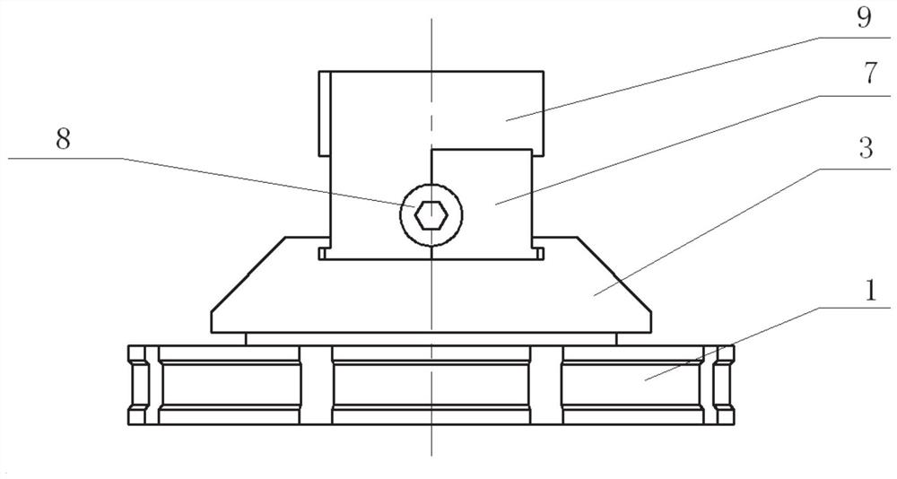
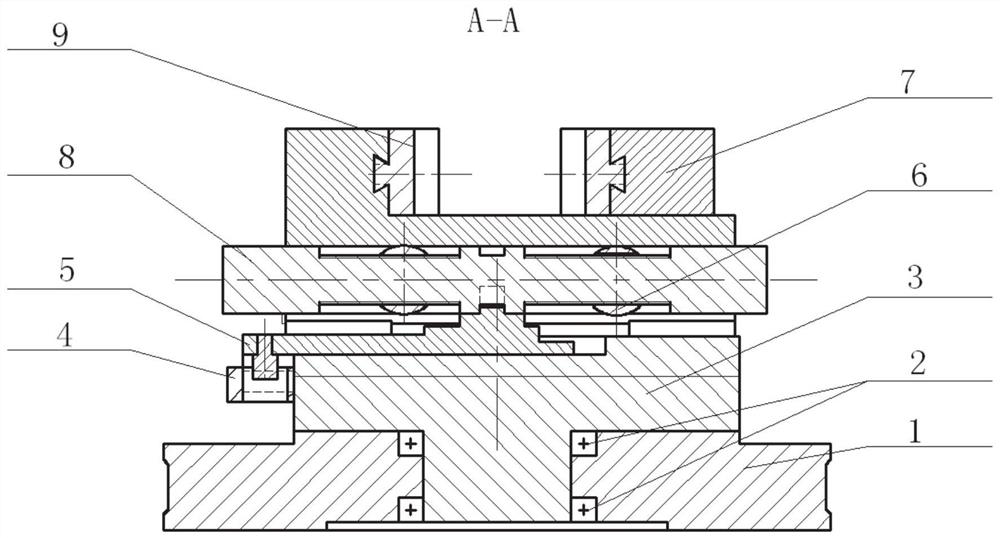
[0051] The assembly diagram of an embodiment of a universal fixture for self-adaptive clamping of blade tip or blade crown process table of the present invention is as follows Figure 1-3 As shown, the part structure diagram is as follows Figure 4-26 shown. A universal fixture for self-adaptively clamping a blade tip or a blade crown process table, comprising a pair of movable blocks 9, a pair of combined fixed blocks 7, an adjustable positioning rod 8, two l...


PUM


Abstract

The invention relates to a universal fixture of a self-adaptive clamping blade tip or blade crown technology table. The universal fixture of the self-adaptive clamping blade tip or blade crown technology table comprises a pair of movable blocks, an adjustable positioning rod, a pair of combined fixed blocks, two locking rings, a positioning block, a limiting block, a base, two cylindrical bearingsand a bottom plate. According to the universal fixture of the self-adaptive clamping blade tip or blade crown technology table, the combined fixed blocks and the base are separated, when a blade tipis directly clamped on the fixture, after the blade tip is clamped, the combined fixed blocks and the base can slide mutually, so that the universal fixture further performs certain float after clamping the blade tip, self-adaptive clamping of parts is realized, and possible clamping stress is reduced. Meanwhile, according to the universal fixture of the self-adaptive clamping blade tip or blade crown technology table, a blade is directly clamped on the fixture, positioning is carried out without adopting a center hole. Finally, according to the universal fixture of the self-adaptive clampingblade tip or blade crown technology table, the universal fixture can directly clamp the blade tip by using a mode of the adjustable positioning rod being matched with the locking rings.

Description

technical field [0001] The invention belongs to the field of fixtures, in particular to a universal fixture for self-adaptively clamping a blade tip or a blade crown process table Background technique [0002] At present, the blade tip fixtures for blade profile processing all use the method of positioning and clamping the top hole of single-drive equipment or the positioning and clamping of the top hole of double-drive equipment. There are two following disadvantages in this method: 1. The tightness will lead to a large clamping stress of the part during the processing process, which will lead to the stress release and deformation of the part after the processing is completed; 2. Regardless of single drive or double drive, the center hole is used for positioning, the size and position of the center hole determine the The qualified rate of blade profile processing, however, there will be deformation after rough machining and heat treatment of most parts, resulting in unquali...

Claims


Application Information

Patent Timeline
Patent Type & Authority Patents(China)
IPC IPC(8): B23Q3/06B25B11/00
CPCB23Q3/06B23Q3/062B25B11/00
Inventor 禹晓敏饶伦徐真琰雷浩强罗培真李晓彦
Owner AECC AERO SCI & TECH CO LTD
Why Eureka
Try Eureka