
Lens for LED light sources

A LED light source and lens technology, applied in optics, nonlinear optics, instruments, etc., can solve the problem of dark edges and corners, and achieve the effect of solving the dark effect of edges and surroundings

Active Publication Date: 2019-03-29
HUIZHOU CHINA STAR OPTOELECTRONICS TECHNOLOGY CO LTD
View PDF7 Cites 0 Cited by
  • Summary
  • Abstract
  • Description
  • Claims
  • Application Information

AI Technical Summary

Problems solved by technology

Solve the problem of dark edges and four corners in the current backlight solution

Method used


Image

  • Lens for LED light sources
  • Lens for LED light sources
  • Lens for LED light sources

Examples


Embodiment Construction

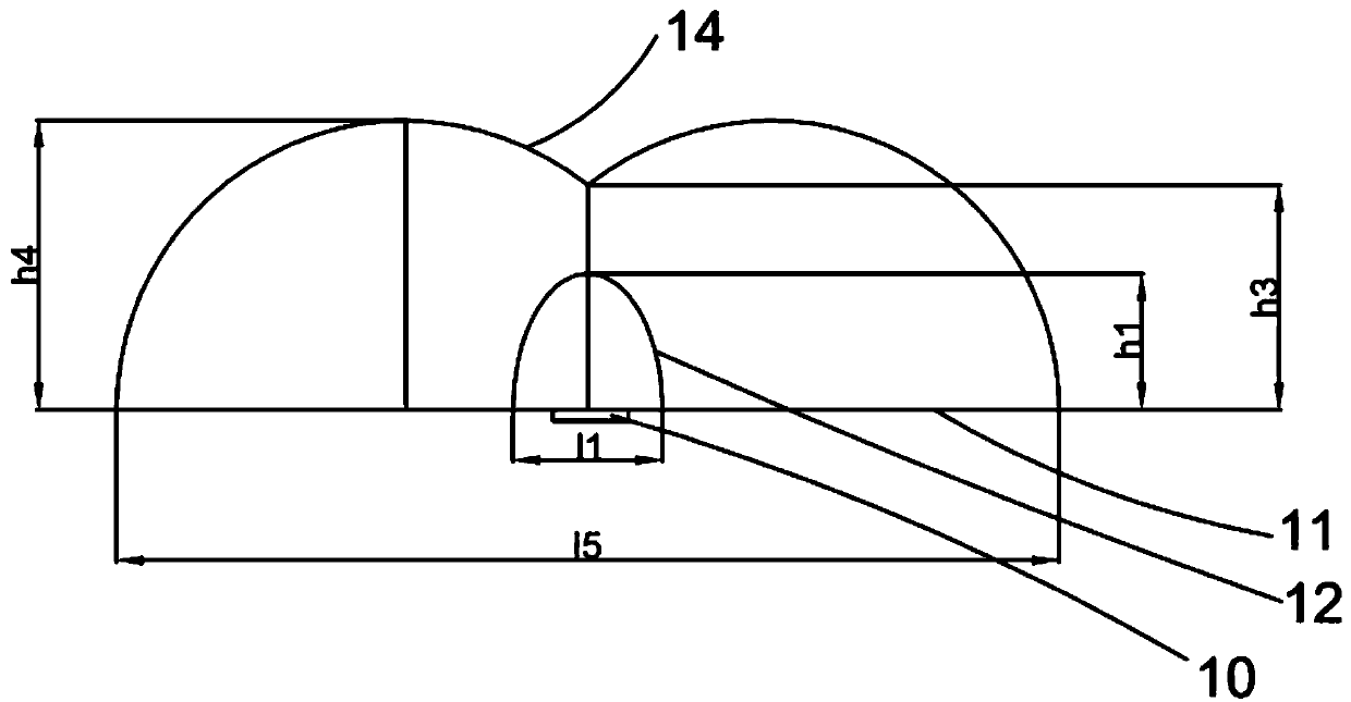
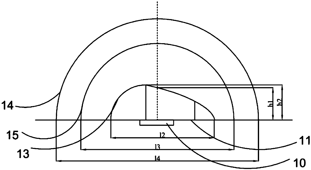
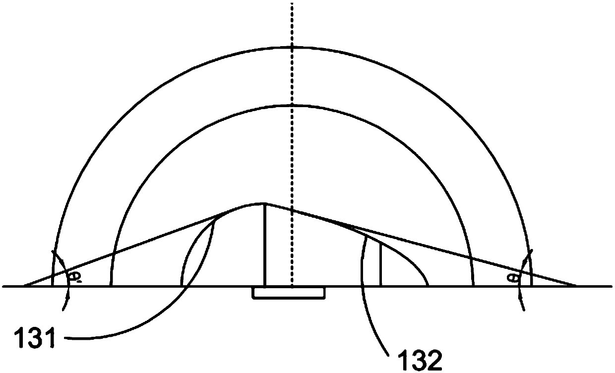
[0034] The following descriptions of the various embodiments refer to the accompanying drawings to illustrate specific embodiments in which the invention may be practiced. The directional terms mentioned in the present invention, such as [top], [bottom], [front], [back], [left], [right], [inside], [outside], [side], etc., are only for reference The orientation of the attached schema. Therefore, the directional terms used are used to illustrate and understand the present invention, but not to limit the present invention. In the figures, structurally similar elements are denoted by the same reference numerals.

[0035] In the direct-lit backlight solution of the prior art, the slope design causes the LED to be far away from the edge, and the overall brightness distribution of the backlight module presents a phenomenon that the edge is darker (especially the four corners are darker), and the overall brightness of the edge LED is compared with the center Insufficient area, showi...


PUM


Abstract

The invention provides a lens for light emitting diode light sources. The lens comprises a bottom surface, a negative camber and a positive camber, wherein the negative camber is formed by upwardly bending the middle part of the bottom surface; the negative camber is a light-in surface; the positive camber is formed by upwardly bending the middle part of the bottom surface; the positive camber isa light-out surface of the lens; and the negative camber is arranged in the positive camber. When an LED packaged by the lens is used for straight-down LED backlight sources of liquid crystal displays, the brightness uniformity and chroma uniformity of the light can be improved, the quality of backlight modules can be improved, and the problem that the edge and four corners are relatively dark inthe existing backlight scheme is solved.

Description

technical field [0001] The invention relates to the field of photoelectric display technology, in particular to an LED lens that can be used for a direct-type liquid crystal display backlight source. Background technique [0002] Traditional cold cathode tube (CCFL) backlights for liquid crystal displays have been gradually replaced by light emitting diode (LED) backlights. However, unlike the line light source cold cathode tube, the LED is a point light source that emits a beam of light at a certain angle. When it is used as a backlight source for a direct-lit liquid crystal display (LCD), hundreds or even thousands of three primary color LEDs are required to be arranged in a certain array to form a surface light source. , and then illuminate the LCD panel. [0003] Converting from point light source to uniform surface light source is the key technology of LED backlight. The uniformity of the surface light source formed by the LED array is closely related to the light int...

Claims


Application Information

Patent Timeline
Patent Type & Authority Applications(China)
IPC IPC(8): G02F1/13357
CPCG02F1/133603G02F1/133606G02F1/133607
Inventor 丘永元
Owner HUIZHOU CHINA STAR OPTOELECTRONICS TECHNOLOGY CO LTD
Learn More