
A method and device for changing the spatial direction of laser focus spot

A technology of focusing light spots and spatial directions, applied in optics, optical components, instruments, etc., can solve problems such as the inability to accurately control the distribution of focal light fields, and achieve the effects of improving accuracy and application range, precise control, and broad application prospects

Active Publication Date: 2020-05-19
HUAZHONG UNIV OF SCI & TECH
View PDF10 Cites 0 Cited by
  • Summary
  • Abstract
  • Description
  • Claims
  • Application Information

AI Technical Summary

Problems solved by technology

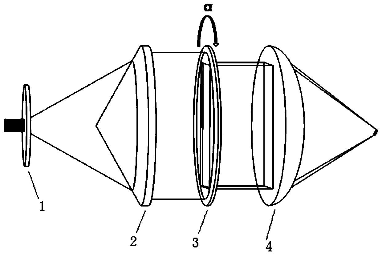
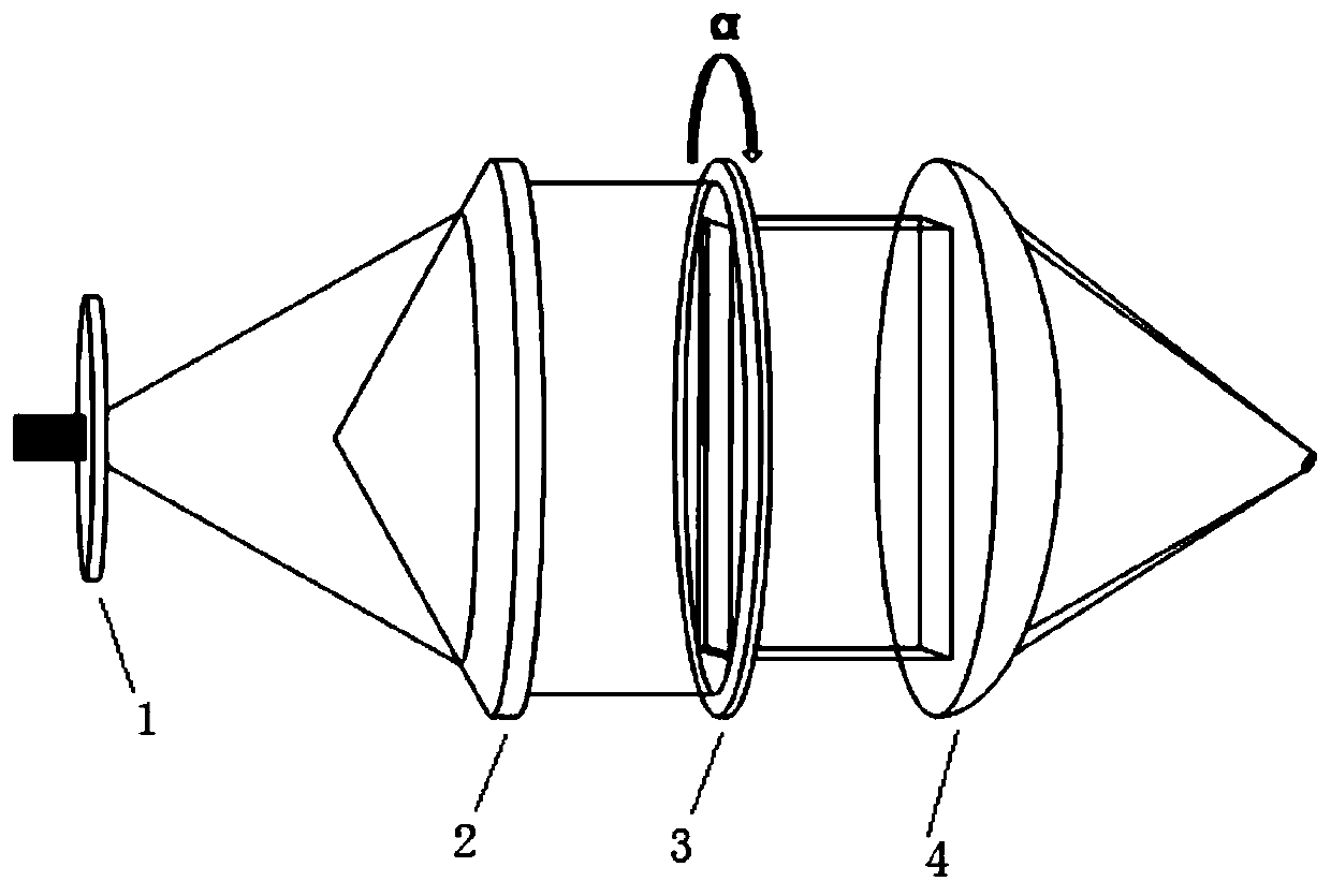
[0005] Aiming at the above defects or improvement needs of the prior art, the present invention provides a method and device for changing the spatial direction of the focused laser spot. to control the distribution of the focal light field, thereby solving the technical problem of being unable to precisely control the distribution of the focal light field

Method used


Image

  • A method and device for changing the spatial direction of laser focus spot
  • A method and device for changing the spatial direction of laser focus spot

Examples


Embodiment Construction

[0029] In order to make the object, technical solution and advantages of the present invention clearer, the present invention will be further described in detail below in conjunction with the accompanying drawings and embodiments. It should be understood that the specific embodiments described here are only used to explain the present invention, not to limit the present invention. In addition, the technical features involved in the various embodiments of the present invention described below can be combined with each other as long as they do not constitute a conflict with each other.

[0030] The method of the invention utilizes the space-time synchronous focusing (SSTF) method to control the spatial direction of the focused light spot. Different from ordinary focusing, the focal plane obtained by the SSTF method has a certain inclination, which will affect the spatial distribution of the light field at the focal point. The direction of tilt is related to the spatial chirp di...


PUM


Abstract

The present invention discloses a method and a device for changing a laser focusing light spot space direction, belonging to the field of laser material processing. The method performs spatial chirp for a laser beam prior to focusing for the laser beam to change an aspect ratio of a light beam to control the inclined angle of the focusing light spot and change the direction of the light beam spatial chirp to change the direction of the focusing light spot inclination. The present invention discloses a device for achieving the method. Through change of the spatial chirp direction of the light beam and the aspect ratio of the light beam, the directions of the two spaces of the laser focusing light spot are controlled so as to solve the technical problem that the distribution of the focus point optical field cannot be accurately controlled and have wide application prospection in the laser accurate and fine processing field.

Description

technical field [0001] The invention belongs to the field of laser material processing, and relates to a method and a device for changing the spatial direction of a laser focused spot using the principle of space-time synchronous focusing, and more specifically, to a method and a device for changing the spatial direction of a laser focused spot. Background technique [0002] In the past few decades, the use of femtosecond lasers for three-dimensional processing in transparent materials has developed into an important branch in the field of laser material processing technology. This method can not only process various optical devices, such as optical waveguides, polarized optical elements, etc., but also can be used to manufacture microfluidic systems and optofluidic systems, etc. The interaction between the laser and the transparent material is related to the nonlinear absorption characteristics of the material for photons, and the active area between the laser and the mater...

Claims


Application Information

Patent Timeline
Patent Type & Authority Patents(China)
IPC IPC(8): G02B27/09G02B27/10G02B27/48
CPCG02B27/0944G02B27/0955G02B27/1093G02B27/48
Inventor 张静宇高骥超刘思垣
Owner HUAZHONG UNIV OF SCI & TECH
Learn More