KDP or DKDP crystal body damage performance high-precision measuring device and measuring method
A measurement method and high-precision technology, which is applied in the direction of measuring devices, instruments, scientific instruments, etc., can solve the problems of inability to obtain the three-dimensional distribution of crystal body damage points, high measurement uncertainty, and mutual occlusion of damage points, so as to achieve convenient debugging, Characterize comprehensive, deliquescence prevention effect
- Summary
- Abstract
- Description
- Claims
- Application Information
AI Technical Summary
Problems solved by technology
Method used
Image
Examples
Embodiment 1
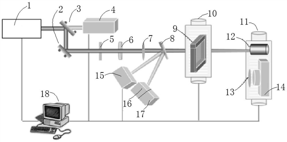
[0052] Such as figure 1 As shown, this embodiment provides a high-precision measurement device for KDP or DKDP crystal body damage performance, including a laser 1, a first mirror 3, a second mirror 2, an energy meter 4, a polarizer 5, and a 1 / 2 wave plate 6. Focusing lens 7, optical wedge 8, CCD camera 15, photocell 16, oscilloscope 17, three-dimensional translation stage 10, ring light source 9, broadband polarizer 13, microscope 14, absorption trap 12 and PC computer 18, also includes two-dimensional The translation stage 11 and two translation stage drive controllers (not shown) connected to the two-dimensional translation stage 11 and the three-dimensional translation stage 10 respectively, the field of view of the microscope 14 can be spliced and larger than the spot on the crystal sample to be measured The size and lateral resolution of the microscope 14 are less than 1 μm, the working distance of the microscope 14 is greater than the thickness of the crystal sample t...
Embodiment 2
[0072] This embodiment is further optimized on the basis of Embodiment 1, specifically:
[0073] In S4, the two-dimensional translation stage 11 and the three-dimensional translation stage 10 are controlled by the PC computer 18, so that the microscope 14 performs three-dimensional tomographic photography of the area to be tested, specifically:
[0074] S4.1: Record the three-dimensional coordinates of the shooting starting point, and control the drive controller of the translation platform through the PC computer 18, thereby controlling the movement of the two-dimensional translation platform 11, so that the microscope 14 laterally photographs a certain tomographic surface of the area to be measured;
[0075] S4.2: After the horizontal shooting of the tomographic surface is completed, the three-dimensional translation stage 10 is controlled by the PC computer 18, so that the three-dimensional translation stage 10 is stepped along the longitudinal direction of the crystal sampl...
Embodiment 3
[0079] This embodiment is further optimized on the basis of Embodiment 1, specifically:
[0080] Described S6 specifically comprises the following steps:
[0081] S6.1: Use 3D image processing software, such as Avizo, Amira, etc., to subtract the picture before damage measurement from the picture after damage measurement to obtain the damage map after pulse action;
[0082] S6.2: Eliminate the impact of the surface factors of the crystal sample to be tested on the pulse effect, solve the problems of repeated statistics of damage points, background light elimination, binarization, etc., and use the image moment algorithm to find the centroid of each scattering point;
[0083]S6.3: Perform three-dimensional reconstruction on all tomographic images of the damage map after excluding the influence, and obtain the three-dimensional distribution of damage points in the crystal body;
[0084] S6.4: Analyze the image obtained after three-dimensional reconstruction to obtain the number...
PUM
 Abstract
Description
Claims
Application Information
 - R&D
- Intellectual Property
- Life Sciences
- Materials
- Tech Scout
- Unparalleled Data Quality
- Higher Quality Content
- 60% Fewer Hallucinations
Browse by: Latest US Patents, China's latest patents, Technical Efficacy Thesaurus, Application Domain, Technology Topic, Popular Technical Reports.
© 2025 PatSnap. All rights reserved.Legal|Privacy policy|Modern Slavery Act Transparency Statement|Sitemap|About US| Contact US: help@patsnap.com

