Eureka AIR delivers breakthrough ideas for toughest innovation challenges, trusted by R&D personnel around the world.

Vertical cavity surface emitting laser

A vertical cavity surface emission and laser technology, which is used in lasers, laser parts, semiconductor lasers, etc. to ensure single-mode operation, reduce parasitic capacitance, and reduce resistance.

Active Publication Date: 2019-03-26
BRIGHTINTELLIGENCE TECH ZHONGSHAN CO LTD
View PDF5 Cites 9 Cited by
  • Summary
  • Abstract
  • Description
  • Claims
  • Application Information

AI Technical Summary

Problems solved by technology

However, when the oxidation-confined layer is located at the antinodes, the scattering loss is clearly a function of the aperture size

Method used


Image

  • Vertical cavity surface emitting laser
  • Vertical cavity surface emitting laser
  • Vertical cavity surface emitting laser

Examples


Embodiment Construction

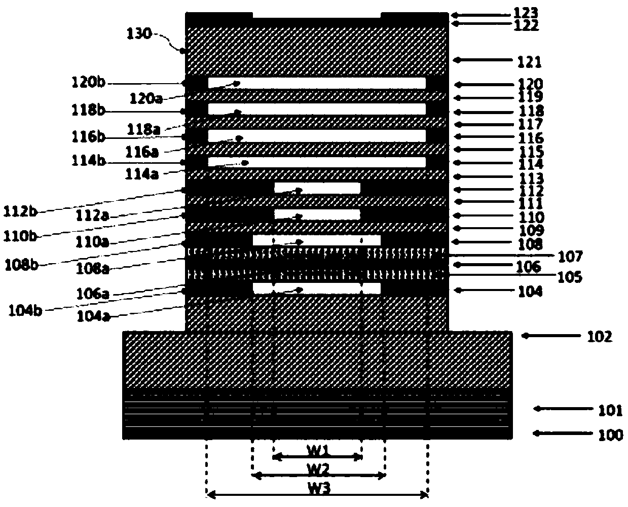
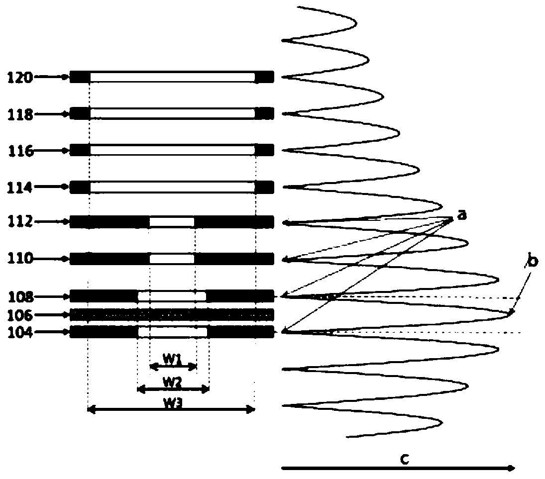
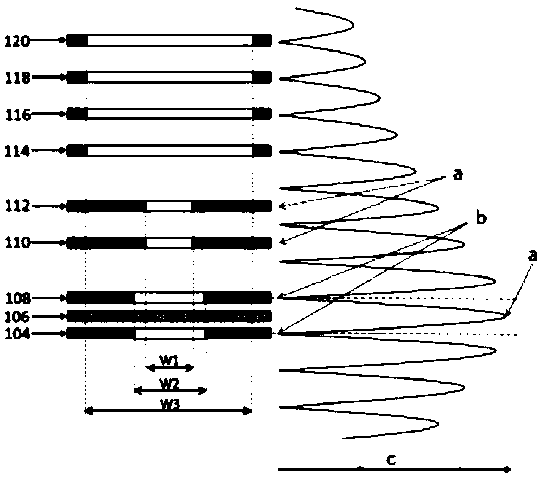
[0036] Such as Figure 1 to Figure 3 As shown, a vertical cavity surface emitting laser described in the present invention will be described in detail with reference to the accompanying drawings.

[0037] figure 1 A cross-sectional structure of a VCSEL according to an embodiment of the present invention is shown. figure 2 enlarged figure 1 and the nearby cross-section shows the first oxidation limited layer 104, the second oxidation limited layer 108, the third oxidation limited layer 110, the fourth oxidation limited layer 112, the fifth oxidation limited layer 114, the sixth oxidation limited layer 116, the seventh Oxidation confinement layer 118 and eighth oxidation confinement layer 120 . figure 2 enlarged figure 1 And the nearby cross-sectional view shows the first oxidation confinement layer 104, the second oxidation confinement layer 108, the third oxidation confinement layer 110, the fourth oxidation confinement layer 112, the fifth oxidation confinement layer 11...


PUM


Abstract

The invention discloses a vertical cavity surface emitting laser comprising a substrate on which a base substrate, a bottom n-type DBR mirror, a first oxidation limiting layer, an n-type guiding spacer layer, an active region layer, a p-type gradual change spacer layer, a second oxidation limiting layer, a first spacer layer, a third oxidation limiting layer, a second spacer layer, a fourth oxidation limiting layer, a third spacer layer, a fifth oxidation limiting layer, a fourth spacer layer, a six oxidation limiting layer, a fifth spacer layer, a seventh oxidation limiting layer, a sixth spacer layer, an eighth oxidation limiting layer, a top p-type DBR mirror, a p-type contact layer, and a p-side electrode are successively disposed. An n-side electrode is disposed on a side of the substrate away from the base substrate. The vertical cavity surface emitting laser can stably achieve single-mode operation, is low in optical loss, low in power consumption and low in parasitic capacitance.

Description

technical field [0001] The invention relates to a vertical-cavity surface-emitting laser, in particular to a high-power single-mode vertical-cavity surface-emitting laser with a DBR reflector of multiple current confinement layers. Background technique [0002] There are several effective current confinement and lateral optical confinement methods in high-power single-mode VCSEL (vertical cavity surface emitting laser), among which the more commonly used methods are buried heterostructure, etching gas column, ion implantation and selective oxidation. Especially VCSELs employing oxidation confinement exhibit excellent performance in terms of modulation bandwidth due to effective current and optical confinement in a small effective volume. Oxidation confinement layers within VCSELs have been used to minimize power dissipation by constricting the current and directing the laser light in the laser mode. However, these oxidation-confined layers produce undesired optical scatteri...

Claims


Application Information

Patent Timeline
Patent Type & Authority Applications(China)
IPC IPC(8): H01S5/183H01S5/187
CPCH01S5/183H01S5/18361H01S5/187H01S5/18311H01S5/1833H01S5/18358H01S5/18377H01S5/3054H01S5/3063H01S5/3432H01S5/04257
Inventor 陈柱元罗玉辉
Owner BRIGHTINTELLIGENCE TECH ZHONGSHAN CO LTD
Why Eureka
Eureka Blog
Learn More