Blade propeller for cargo ship

A technology for propellers and cargo ships, which is applied in the direction of rotating propellers, ship propulsion, ship parts, etc., can solve the problems of adverse effects of ship navigation development, large energy loss, low work efficiency, etc., to weaken the radial migration effect, improve power, improve performance effect

Inactive Publication Date: 2019-03-26
ZHEJIANG OCEAN UNIV
View PDF12 Cites 7 Cited by
  • Summary
  • Abstract
  • Description
  • Claims
  • Application Information

AI Technical Summary

Problems solved by technology

[0003] The propeller is the power source device for the ship to advance. During the ship's navigation, the ship is easily affected by factors such as the size of the wind and waves, the load capacity, and the surface finish. Therefore, the power propeller of the ship is particularly important. The existing power propellers have large energy loss, The problem of low work efficiency has a certain adverse effect on the development of ship navigation

Method used


Image

  • Blade propeller for cargo ship
  • Blade propeller for cargo ship
  • Blade propeller for cargo ship

Examples


Embodiment 1

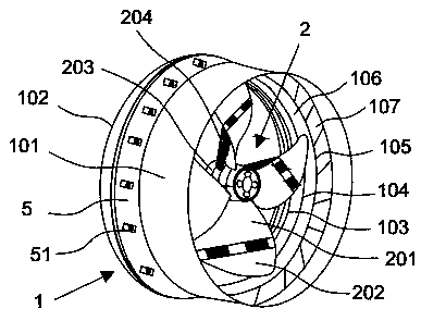
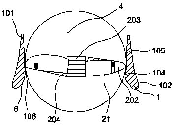
[0029] like Figure 1-7 As shown, the solution adopted by the present invention to achieve the above object is: a split-bladed propeller for cargo ships, comprising a draft tube 1 and a propeller 2 with at least one blade 21, the blade 21 comprising a flap in the front end region 202, the propeller 2 is arranged in the draft tube 1 in the following manner: a turbulence groove 106 along the circumferential direction of the draft tube 1 is formed between the flap 202 in the front end region of the blade 21 and the inner wall 6 of the draft tube 1 , the water inlet end of the diversion pipe 1 is provided with a protective cover 7, and one end surface of the protective cover 7 is evenly distributed with a retaining bar 73 ring cloth connected to the surface of the ring 74, the ring 74 is provided with a rotating ball 75, and the protective cover 7 is provided with Evenly distributed on the blade 76 on the ball 75, the ball 75 can rotate in the ring 74. By arranging the propeller ...

Embodiment 2

[0042] The working principle of a split-bladed propeller for a cargo ship in the present invention is as follows: the propeller 2 is installed in the guide tube 1, so that the flap 202 in the front end region of the blade 21 and the inner wall 6 of the guide tube 1 form a The turbulence groove 106 in the circumferential direction of the flow pipe 1 is adjusted to expand and contract the telescopic push rod 204, so that the paddle 21 is turned to a suitable angle, and the propeller 2 is started to rotate. The formed rotating water flow drives the auxiliary paddle 3 to rotate, which improves the overall power.

Embodiment 3

[0044] Comparative Test

[0045] Get respectively a kind of cargo ship of the present invention with split-blade propeller and the common ship propeller on the market to compare, and at the same time, in the same sea area, drop a kind of cargo ship with split-blade propeller of the present invention and ship with paddle on the market to test respectively, During this process, power, open water efficiency, and stability are monitored.

[0046]

[0047] Result: Through the above experiments, it can be concluded that a kind of split-blade propeller for cargo ships of the present invention is better than ordinary ship propellers on the market. During use, the split-blade propeller for cargo ships of the present invention has better power, open water efficiency, stability The performance is better than that of ordinary ship oars on the market, so this device can better provide power for ships.


PUM


Abstract

The invention discloses a blade propeller for a cargo ship. The blade propeller for the cargo ship comprises a flow guide pipe and a propeller body provided with at least one propeller blade. Each propeller blade comprises a folding wing in a front-end area. The propeller body is arranged in the flow guide pipe in the following manner: a turbulent flow groove in the circumferential direction of the flow guide pipe is formed between the folding wings in the front-end areas of the propeller blades and the inner wall of the flow guide pipe; a protective cover is arranged at the water inlet end ofthe flow guide pipe; blocking bars are uniformly distributed inside one end face of the protective cover and are annularly connected with the surface of a circular ring; a rotary ball is arranged inthe circular ring; the protective cover is internally provided with blades uniformly distributed on the rotary ball; and the rotary ball can rotate in the circular ring. The blade propeller for the cargo ship is high in overall performance, reasonable in structure design, small in energy loss, small in sea wave impact during operating in water, long in service life, stable in operation in water and high in reliability and working efficiency.

Description

technical field [0001] The invention relates to the technical field of marine attachments, in particular to a segmented propeller for cargo ships. Background technique [0002] A ship is a man-made means of transportation that primarily operates in geographical waters. In addition, civilian ships are generally called ships, military ships are called ships, and small ships are called boats or boats, which are collectively called ships or boats. The interior mainly includes accommodation space, support structure and drainage structure, and has a propulsion system that utilizes external or self-contained energy. The appearance is generally a streamlined envelope that is conducive to overcoming fluid resistance. The materials are constantly updated with the advancement of science and technology. In the early days, they were natural materials such as wood, bamboo, and hemp. In modern times, they are mostly steel, aluminum, glass fiber, acrylic, and various composite materials. ...

Claims


Application Information

Patent Timeline
Patent Type & Authority Applications(China)
IPC IPC(8): B63H1/14B63H1/26B63H1/28B63H5/16
CPCB63H1/14B63H1/26B63H1/28B63H5/165
Inventor 淦学甄
Owner ZHEJIANG OCEAN UNIV
Why Eureka
Try Eureka