Cement nail gun
A nail gun and cement technology, applied in nailing tools, manufacturing tools, etc., can solve the problems of increased equipment and cost, inconvenient transportation, poor portability, etc., and achieve the effects of stable force, exquisite overall design, and simple triggering.
- Summary
- Abstract
- Description
- Claims
- Application Information
AI Technical Summary
Problems solved by technology
Method used
Image

Examples
Embodiment 1
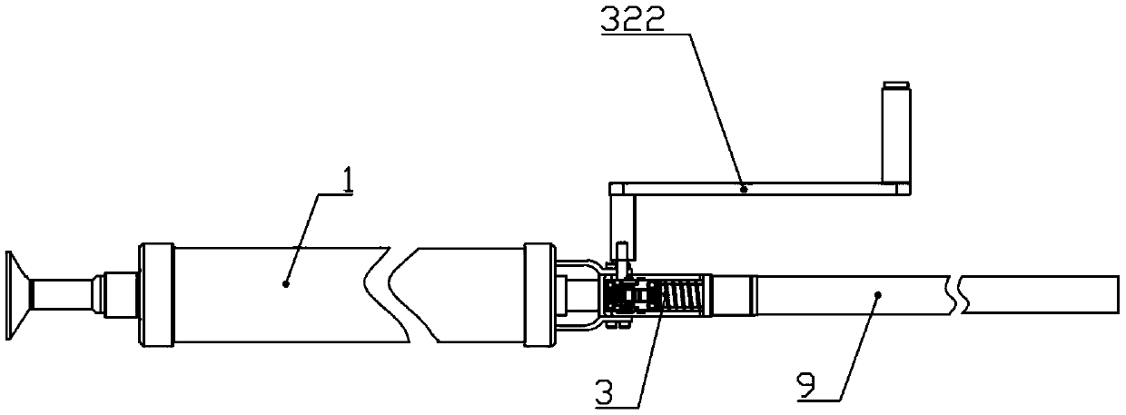
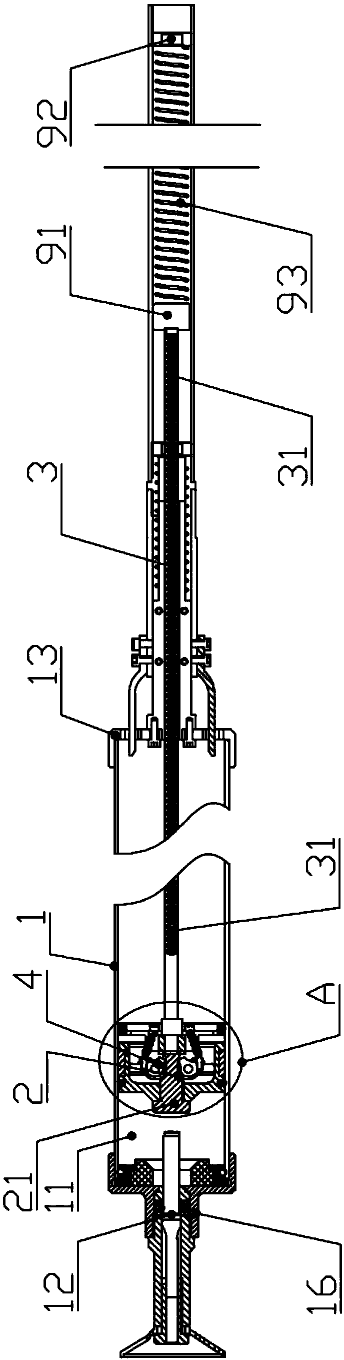
[0048] Embodiment one: if Figure 1-12 As shown, a cement nail gun includes a cylinder 1, and a piston assembly 2 is slidably arranged in the cylinder 1. The piston assembly 2 is used to discharge the air at the rear end of the piston assembly 2 and form a vacuum at the front end of the compression piston assembly 2 during the movement. cavity 11; the front end of the piston assembly 2 is provided with an impact head 21, and the front end of the impact head 21 is provided with a striker 12; the rear end of the piston assembly 2 is connected with a driving device 3, and the driving device 3 is used to drive the piston assembly 2 in the The cylinder 1 moves and fires the striker 12 to move.
[0049] The technical solution specifically describes a cement nail gun that utilizes the pressure difference between the inside and outside of the atmosphere as power for nailing operations. Specifically, in actual use, when the driving device 3 drives the piston assembly 2 to move toward ...
Embodiment 2
[0091] Embodiment two, such as Figure 5 and Figure 8 As shown, this embodiment is basically the same as Embodiment 1, and the difference lies in that "the mounting hole 331 is formed on one side of the locking pawl 33, and the upper end of the mounting seat 34 is provided with a limiting pressing piece 35, which limits A tension spring 36 is arranged between the position pressing piece 35 and the mounting hole 331, and this part of the technical solution can be replaced by "a return torsion spring abuts between the mounting seat 34 and the locking pawl 33." 332". That is to say, a reset torsion spring can be arranged at the front end of the locking pawl 33 , so that there is always a force to drive the locking pawl 33 against the rack pull rod 31 . This makes the sliding process of the rack rod 31 smoother and labor-saving.
Embodiment 3
[0092] Embodiment 3, this embodiment is basically the same as Embodiment 1, the difference lies in that the rear limit pin 37 also has a function as a signal for the rack pull rod 31 to move to the set position. Specifically, at this time, the tooth surface height of the rack pull rod 31 should be designed "from high to low" from the front end to the rear end. When the rack pull rod 31 moves to the set position, the distance between the lower end of the locking pawl 33 and the rear limit pin 37 becomes smaller and smaller as the tooth surface is lifted. 31 just can't move, and performance is exactly that hand wheel can not be shaken again externally, and this moment then represents rack pull bar 31 and can enter the percussion step in place.
[0093] Such a design has a function of prompting and limiting. Can tell the user when to stop. In this embodiment, "from high to low" does not represent a linear change process, and it can also be one of the teeth on the rack rod 31. I...
PUM
 Abstract
Description
Claims
Application Information
 - Generate Ideas
- Intellectual Property
- Life Sciences
- Materials
- Tech Scout
- Unparalleled Data Quality
- Higher Quality Content
- 60% Fewer Hallucinations
Browse by: Latest US Patents, China's latest patents, Technical Efficacy Thesaurus, Application Domain, Technology Topic, Popular Technical Reports.
© 2025 PatSnap. All rights reserved.Legal|Privacy policy|Modern Slavery Act Transparency Statement|Sitemap|About US| Contact US: help@patsnap.com