Mop with inverted scraper

An inverted scraper and mop technology, applied in the field of mops, can solve the problems of inconvenient use and frequent cleaning, and achieve the effects of convenient use, improved mopping efficiency, and reduced cleaning times

Inactive Publication Date: 2019-03-26
SHENZHEN LOTUT INNOVATION DESIGN CO LTD
View PDF17 Cites 1 Cited by
  • Summary
  • Abstract
  • Description
  • Claims
  • Application Information

AI Technical Summary

Problems solved by technology

[0003] However, there will be a disadvantage when using this kind of mop. The contact area between the sponge body and the ground tends to be basically fixed. When cleaning a small area, some dust or small particles of garbage will adhere to the mop. It needs to be very frequent. If you don’t clean it up, when you go to mop other places, the dust on the mop will leave a gray mark at the position where the mopping floor first touches the ground. , the dust moves forward with the sponge body, when pulled back, the dust that has not adhered to the sponge body will stay on the ground, forming a gray mark, which is inconvenient to use

Method used


Image

  • Mop with inverted scraper
  • Mop with inverted scraper
  • Mop with inverted scraper

Examples


Embodiment 1

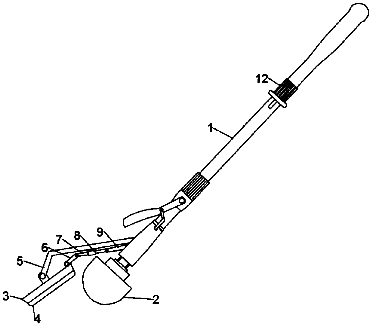
[0023] see Figure 1~3 , in an embodiment of the present invention, a mop with an inverted scraper includes a mop body; the mop body includes a handle 1 for holding and a mop head 2 for mopping the floor, and the mop body is provided with The upper end of the duct plate 3 is hinged to the fixed rod 5 through the inverted scraper 3 connected with the fixed rod 5 , and an adjustment mechanism is installed on the right side of the inverted scraper 3 .

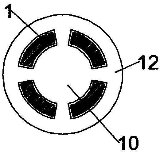
[0024] The adjusting mechanism includes a first connecting rod 6, a movable rod 7, a second connecting rod 9 and a push rod 10. The movable rod 7 runs through the collar 8 fixed on the lower end of the fixed rod 5 and is slidably connected with the inner wall of the collar 8, and moves One end of the rod 7 is connected with one end of the first connecting rod 6, the other end of the first connecting rod 6 is connected with the inverted scraper 3, the other end of the movable rod 7 is connected with one end of the second connecting...

Embodiment 2

[0030] see Figure 4 The difference between the second embodiment and the first embodiment is that the lower end of the inverted scraper 3 is symmetrically equipped with pulleys, and an endless belt 13 is rotatably connected to the pulleys, and an adjusting handle 14 is fixedly installed on the rotating shaft of one of the pulleys. The adjustment handle 14 is handed over with an L-shaped rod, which is inserted into the clamping hole provided on the inverted scraper 3. When the L-shaped rod breaks away from the clamping hole, the adjustment of the endless belt 13 can be realized. The outside of the endless belt 13 A sponge is installed.


PUM


Abstract

The invention discloses a mop with an inverted scraper. The mop comprises a mop body. The mop body comprises a handle and a mop head, wherein the handle is held with hands, and the mop head is used for mopping a floor; the mop body is provided with the inverted scraper which is connected through a fixing rod; the upper end of a pipe guiding plate is hinged to the fixing rod, and an adjusting mechanism is installed on the right side of the inverted scraper. The mop is novel in design, when the mop body is pushed forwards, a pushing ring moves downwards under the action of the hands, a movable rod is driven by a second connecting rod to move towards the inverted scraper and then drives the inverted scraper to be overturned upwards through a first connecting rod, and the inverted scraper stays in an upturned state at that time, so that no influence is generated when the mop is normally used for mopping the floor. When the mop body is pulled backwards, the pushing ring moves upwards underthe action of the hands, the inverted scraper rotates to enable one end of the inverted scraper to abut against the ground, correspondingly dust staying on the ground is removed again, a cleaning effect is achieved, the mop is convenient to use, the frequency of cleaning the mop is reduced, and the efficiency of mopping the floor is improved.

Description

technical field [0001] The invention relates to a mop, in particular to a mop with an inverted scraper. Background technique [0002] In real life, the mop is a must for the family and plays a key role in cleaning the ground. The end of the existing mop is provided with a sponge for cleaning the ground. The upper end of the sponge is provided with a rollable cylindrical rod , used to squeeze the sponge body to achieve the effect of removing water, easy to use. [0003] However, there will be a disadvantage when using this kind of mop. The contact area between the sponge body and the ground tends to be basically fixed. When cleaning a small area, some dust or small particles of garbage will adhere to the mop. It needs to be very frequent. If you don’t clean it up, when you go to mop other places, the dust on the mop will leave a gray mark at the position where the mopping floor first touches the ground. , the dust moves forward with the sponge body, and when it is pulled ba...

Claims


Application Information

Patent Timeline
Patent Type & Authority Applications(China)
IPC IPC(8): A47L13/20A47L13/24A47L13/257A47L13/42
CPCA47L13/20A47L13/24A47L13/257A47L13/42
Inventor 高威其他发明人请求不公开姓名
Owner SHENZHEN LOTUT INNOVATION DESIGN CO LTD
Why Eureka
Try Eureka