Switched capacitor subtraction circuit and sensor device

A capacitive circuit and subtraction circuit technology, which is applied to amplifiers with semiconductor devices/discharge tubes, amplifiers, electrical components, etc., can solve problems such as unreasonable solutions to reduce common-mode errors

Pending Publication Date: 2019-03-22
SHENZHEN FINGERCHIP INTELLIGENT TECH
View PDF10 Cites 0 Cited by
  • Summary
  • Abstract
  • Description
  • Claims
  • Application Information

AI Technical Summary

Problems solved by technology

[0004] The purpose of the present invention is to provide a switched capacitor subtraction circuit and a sensor device, aiming to solve the problem of unreasonable solutions for reducing common-mode errors in the traditional technical solutions

Method used


Image

  • Switched capacitor subtraction circuit and sensor device
  • Switched capacitor subtraction circuit and sensor device

Examples


Embodiment Construction

[0025] In order to make the object, technical solution and advantages of the present invention clearer, the present invention will be further described in detail below in conjunction with the accompanying drawings and embodiments. It should be understood that the specific embodiments described here are only used to explain the present invention, not to limit the present invention.

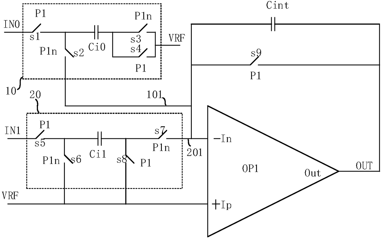
[0026] figure 1 It shows a switched capacitor subtraction circuit that can be applied to sensor devices such as fingerprint readers provided by a preferred embodiment of the present invention, and the circuit includes an operational amplifier OP1, a first capacitor circuit 10, a second capacitor circuit 20, and an integrating capacitor Cint .

[0027] Its non-inverting input terminal +Ip of operational amplifier OP1 is connected to reference voltage VRF; The first capacitor circuit 10 is connected to the first input signal IN0 and reference voltage VRF, and the output terminal 101 of the first cap...


PUM


Abstract

The invention provides a switched capacitor subtraction circuit and a sensor device. The circuit comprises an operational amplifier, a first capacitive circuit, a second capacitive circuit, and an integrating capacitor. The non-inverting input terminal of the operational amplifier is connected to a reference voltage. The first capacitor circuit is connected to a first input signal and the reference voltage. The output end of the first capacitor circuit has a first polarity. The second capacitor circuit is connected to a second input signal and the reference voltage. The output end of the second capacitor circuit has a second polarity opposite to the first polarity. There is a difference value between the first input signal and the second input signal. The first capacitor circuit and the second capacitor circuit are simultaneously discharged to transfer respective stored amounts of power to the integrating capacitor. The common-mode removal and subtraction are achieved by separately acquiring two input signals having difference values, and transferring the stored electric charge to the integrating capacitor simultaneously in the form of an opposite polarity, respectively.

Description

technical field [0001] The invention belongs to the technical field of switched capacitors, in particular to a switched capacitor subtraction circuit and sensor equipment. Background technique [0002] Some electronic systems may include signal paths for processing signals. For example, a biometric system may include an integrated circuit (IC) with a signal channel for processing signals received from a biometric sensor. A signal path may have common-mode errors that may arise from various sources, such as common-mode noise and / or systematic bias associated with the signal path. Common-mode errors can degrade the integrity of the data processed by the signal path. [0003] For example, in biometric system implementations, common mode errors in the signal paths may produce progressive pattern errors that cause visual artifacts in biometric images generated using the biometric system. In specific applications, reducing common-mode errors by using differential signals, incre...

Claims


Application Information

Patent Timeline
Patent Type & Authority Applications(China)
IPC IPC(8): H03F3/45
CPCH03F3/45977H03F2203/45012
Inventor 余俊易海平
Owner SHENZHEN FINGERCHIP INTELLIGENT TECH
Why Eureka
Try Eureka