Pneumatic transporter with high accuracy steering control and steering control method thereof
A technology for steering control and trucks, applied to steering mechanisms, control devices, vehicle components, etc., can solve the problems that trucks are difficult to meet requirements, the application of trucks is limited, and occupy a large space, etc., and achieve simple structure, no pollution, fast response effect
- Summary
- Abstract
- Description
- Claims
- Application Information
AI Technical Summary
Problems solved by technology
Method used
Image
Examples
specific Embodiment approach 1
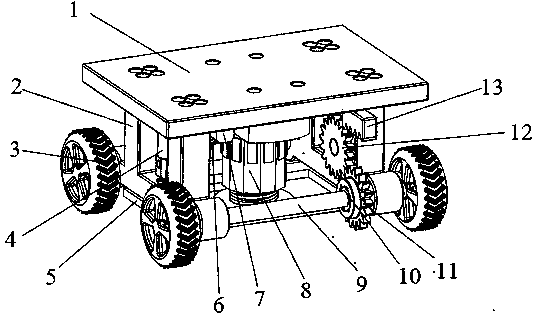
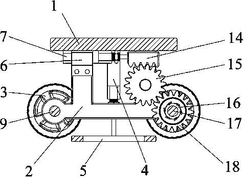
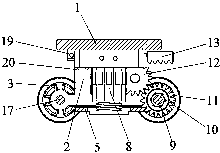
[0035] Specific implementation mode one: combine Figure 1~Figure 14 This specific embodiment will be described. This embodiment provides a specific implementation of a high-precision steering control pneumatic truck; the high-precision steering control pneumatic truck includes a loading platform 1, a vehicle frame 2, wheels 3, a lifting cylinder assembly 4, Lift push plate 5, rear drive cylinder support seat 6, rear drive cylinder 7, pneumatic helical steering driver 8, front wheel axle 9, front pawl disc 10, front ratchet gear 11, front drive gear 12, front drive rack 13, Rear drive tooth bar 14, rear transmission gear 15, rear ratchet disc 16, rear wheel axle 17, rear ratchet gear 18, front drive cylinder 19 and front drive cylinder support seat 20.
[0036] The loading platform 1 is screwed on the vehicle frame 2, and the wheels 3 are connected respectively to the two ends of the front wheel axle 9 and the rear wheel axle 17; the lifting cylinder assembly 4 includes a cyl...
specific Embodiment approach 2
[0040] Specific implementation mode two: combination Figure 15~Figure 16 This specific embodiment will be described. The difference between this specific embodiment and the first specific embodiment is that: the vibration-exciting flange nut 8-4 can be d 33 Excitation Mode Flange Nut 8-401; the d 33 Vibration mode flange nut 8-401, on which is provided with cage one 8-401-1, vibration cavity two 8-401-2, piezoelectric stack 8-401-3, said piezoelectric stack 8-401 -3 is arranged between the first cage 8-401-1 and the second vibration cavity 8-401-2, so that the second vibration cavity 8-401-2 can generate radial vibration, the number of which is 2n, and n is An integer greater than 1, in this specific embodiment n is 2; the d 33 There are also two ventilation holes 8-401-4 on the flange nut 8-401 in excitation mode, which communicate with the two ventilation holes 8-3-3 inside the piston rod 8-3 respectively; the d 33 The internal thread 2 8-401-5 set by the flange nut 8-4...
specific Embodiment approach 3
[0041] Specific implementation mode three: combination Figure 17~Figure 18 This specific embodiment will be described. The difference between this specific embodiment and the first specific embodiment is that: the vibration-exciting flange nut 8-4 can be d 15 Excitation Mode Flange Nut 8-402; the d 15 The vibration mode flange nut 8-402 is provided with a cage two 8-402-1, a vibration cavity three 8-402-2, the d 15 The shear piezoelectric ceramic 8-402-3 set by the flange nut 8-402 of the excitation mode is pasted between the cage two 8-402-1 and the vibration cavity three 8-402-2, so that the vibration cavity Three 8-402-2 generate axial vibration, the number of which is 2n, n is an integer greater than 1, and n is 2 in this specific embodiment; the d 15 The flange nut 8-402 of excitation mode is also provided with two air holes 3 8-402-4, which communicate with the two air holes 8-3-3 inside the piston rod 8-3 respectively; the d15 excitation mode The internal thread th...
PUM
 Abstract
Description
Claims
Application Information
 - R&D
- Intellectual Property
- Life Sciences
- Materials
- Tech Scout
- Unparalleled Data Quality
- Higher Quality Content
- 60% Fewer Hallucinations
Browse by: Latest US Patents, China's latest patents, Technical Efficacy Thesaurus, Application Domain, Technology Topic, Popular Technical Reports.
© 2025 PatSnap. All rights reserved.Legal|Privacy policy|Modern Slavery Act Transparency Statement|Sitemap|About US| Contact US: help@patsnap.com


