
Battery cell connecting piece welding mechanism and welding method thereof

A welding mechanism and welding method technology, applied in welding equipment, laser welding equipment, circuits, etc., can solve the problems of welding slag generated by the connecting piece of the battery cell and the top cover pole, hidden dangers of battery safety, and affecting the performance and quality of the battery. Guaranteed functionality and strength, less metal spatter, improved performance quality and safety

Pending Publication Date: 2019-03-19
JIANGSU ZENIO NEW ENERGY BATTERY TECH CO LTD
View PDF17 Cites 5 Cited by
  • Summary
  • Abstract
  • Description
  • Claims
  • Application Information

AI Technical Summary

Problems solved by technology

[0005] The technical problem to be solved by the present invention is to provide a welding mechanism for the cell connecting piece and a welding method for the connecting piece of the battery in view of the deficiencies in the prior art, so as to solve the problem that occurs when the connecting piece of the battery cell and the pole of the top cover are welded. Welding slag, which will affect the performance and quality of the battery, and make the battery a technical problem with potential safety hazards

Method used


Image

  • Battery cell connecting piece welding mechanism and welding method thereof
  • Battery cell connecting piece welding mechanism and welding method thereof
  • Battery cell connecting piece welding mechanism and welding method thereof

Examples


Embodiment 1

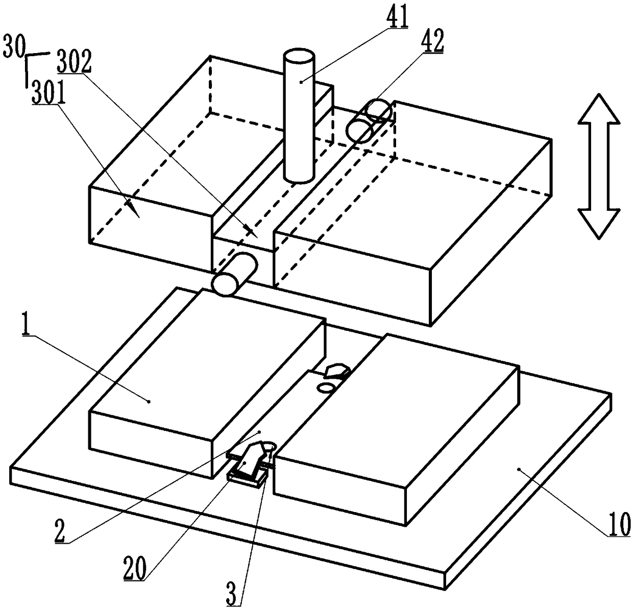
[0040] see figure 1 , which is a structural schematic diagram of a cell connecting piece welding mechanism provided in this embodiment. The cell connecting piece welding mechanism includes:

[0041] A welding station 10, the welding station 10 is used to place the electric core 1 with the connecting piece 2 installed;

[0042] A laser welding assembly 20, the laser welding assembly 20 is installed on the welding table 10;

[0043] A dust removal cover 30, the dust removal cover 30 is movably sealed on the electric core 1 and the laser welding assembly 20;

[0044] Wherein, the dust removal cover 30 includes a cell accommodating chamber 301 for accommodating the electric core 1, and a welding chamber 302 for welding the connecting piece 2; The tuyere is sealed and installed with a blowing pipe 41 communicating with the welding chamber 302, and the air extraction hole is sealed and installed with an exhausting pipe 42 communicating with the welding chamber 302; the end of the ...

Embodiment 2

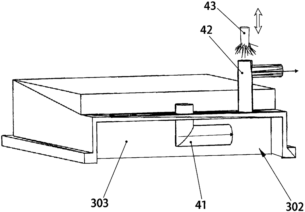
[0050] see figure 2 , which is a cross-sectional view of a dust removal hood in this embodiment;

[0051] In order to further optimize this technical solution, it is preferred on the basis of the above-mentioned embodiment one, such as figure 2 As shown, the air extraction hole is opened on the top of the welding chamber 302 , and the air extraction pipe 42 extends to directly above the welding point 3 of the connecting piece 2 through the air extraction hole. Specifically, through this structural design, the exhaust pipe 42 can adopt a coaxial vacuum suction method to extract welding slag or dust from above the welding point 3, thereby achieving the purpose of eliminating welding slag.

Embodiment 3

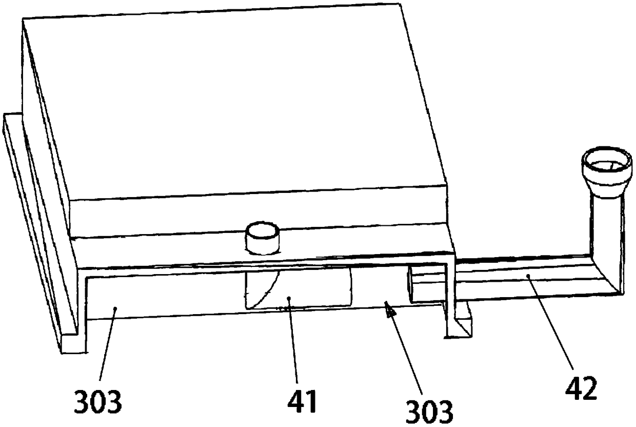
[0053] see image 3 , which is a cross-sectional view of another dust cover in this embodiment;

[0054] In order to further optimize this technical solution, preferably on the basis of the first embodiment above, the air extraction hole is opened on the side of the welding chamber 302, and the air extraction pipe 42 extends to the welding point of the connecting piece 2 through the air extraction hole 3 sideways. Concrete, utilize this structural design, the air extraction port of air extraction pipe 42 can be arranged on the side of welding point 3 as much as possible, because the air blowing port of air blowing pipe 41 is facing the air extraction port of air extraction pipe 42, avoids that the air flow turns and reverses, This avoids slowing down of the airflow speed, thereby improving the performance and efficiency of welding slag removal.


PUM


Abstract

The invention discloses a battery cell connecting piece welding mechanism. The welding mechanism comprises a welding table, a laser welding assembly and a dust removal cover; the dust removal cover comprises a battery cell accommodating chamber and a welding chamber; an air inlet hole and an air suction hole are formed in the welding chamber, the air inlet hole is provided with an air blowing pipecommunicating with the welding chamber, and the air suction hole is provided with an air suction pipe communicating with the welding chamber. The mechanism is provided with the dust removal cover, and the welding chamber of the dust removal cover is in communication with a protective gas conveying device and a vacuum generating device through the air blowing pipe and the air suction pipe respectively; when the laser welding assembly is used for carrying out laser welding on a connecting piece of a battery cell and a pole column of a top cover, the protective gas conveying device introduces protective gas into the welding chamber at the same time, the vacuum generating device is used for sucking metal spatters produced by welding and welding slag formed by the metal spatters from the welding chamber in a negative pressure vacuum pumping mode, so that the purpose of eliminating the welding slag is achieved, adverse effects on the battery cell caused by the welding slag are avoided, andtherefore the safety of a battery is improved while the performance quality of the battery is guaranteed.

Description

technical field [0001] The present application relates to the technical field of battery tab welding, in particular to a battery connecting piece welding mechanism and a welding method thereof. Background technique [0002] In the production of lithium-ion batteries, it is necessary to weld the connecting piece of the battery cell to the pole of the battery top cover. Increase the fusion width. In addition, due to the thicker size of the connection piece, in order to meet the requirements of penetration depth and fusion width at the same time, a larger welding power is required when welding the connection piece. [0003] In the current connecting piece welding process, the single fiber continuous laser welding method is mainly used to realize the welding between the cell connecting piece and the top cover pole. In the process of high-power deep melting of fiber laser welding, the molten pool is unstable, the reaction is strong, and defects such as metal splashes and explosi...

Claims


Application Information

Patent Timeline
Patent Type & Authority Applications(China)
IPC IPC(8): B23K26/22B23K26/70B23K26/16B23K26/12B23K101/38
CPCB23K26/127B23K26/16B23K26/22B23K26/702H01M50/536H01M10/052Y02E60/10
Inventor 卢军太李龙曾志恒
Owner JIANGSU ZENIO NEW ENERGY BATTERY TECH CO LTD
Learn More