Fuel cell bipolar plate with interrupt structure

A fuel cell and bipolar plate technology, applied in the direction of fuel cells, battery electrodes, structural parts, etc., can solve the problems of MEA film damage, battery failure, and no prevention of cooling water bypass flow, etc., to improve durability and The effect of stability and easy structure

Pending Publication Date: 2019-03-15
SUNRISE POWER CO LTD
View PDF9 Cites 3 Cited by
  • Summary
  • Abstract
  • Description
  • Claims
  • Application Information

AI Technical Summary

Problems solved by technology

The disadvantage is that although the bypass flow of reactants can be improved, since the MEA sealing frame is bent at the nested protrusion, the tangential stress of the MEA sealing frame at the bend is relatively large, which can easily cause the membrane in the middle of the MEA to be damaged. , so that the battery fails; on the other hand, the patented technology does not provide measures to prevent the cooling water bypass circulation
Its disadvantage is that although the bypass flow of reactants can be significantly improved, the thickness of the increased filling material is not easy to control. If the thickness is too large, the contact pressure between the pole plate and the MEA will decrease, which will lead to an increase in the internal resistance of the battery. large; on the other hand, the patent does not give measures to prevent the bypass flow of cooling water

Method used


Image

  • Fuel cell bipolar plate with interrupt structure
  • Fuel cell bipolar plate with interrupt structure
  • Fuel cell bipolar plate with interrupt structure

Examples


Embodiment 1

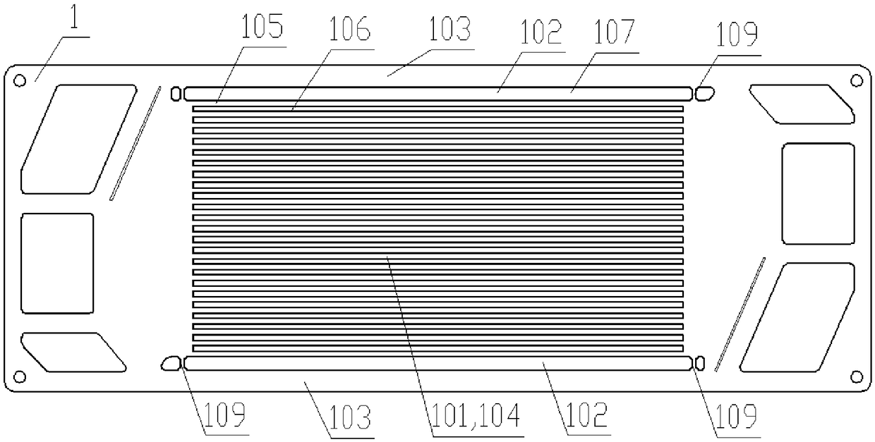
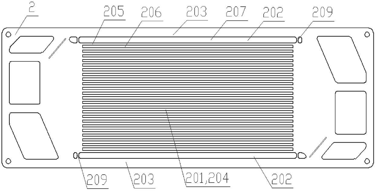
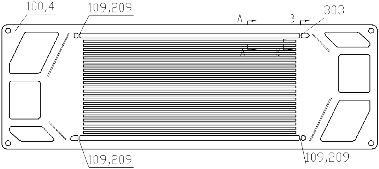
[0025] Such as Figure 1 to Figure 5As shown, the bipolar plate 100 includes a cathode plate 1 and an anode plate 2, the space between the cathode plate 1 and the anode plate 2 forms a cooling water flow field, and the space between the cathode plate 1 and the anode plate 2 and the membrane electrode 4 are respectively The cathode flow field and the anode flow field are formed; the centerlines of each flow channel in the active area of ​​the cathode plate 1 and the anode plate 2 are aligned, the flow channel is a flat flow channel, and the isolation area is 0.04mm higher than the ridge of the active area flow channel. The cooling water discontinuity structure 303 includes the groove 109 on the cathode isolation area and the groove 209 on the anode isolation area corresponding to the groove 109 on the cathode isolation area on the anode plate isolation area, respectively formed in the cooling water cavity Boss, four grooves 109 on the cathode isolation area, four grooves 209 on...

Embodiment 2

[0027] The structure of the second embodiment is the same as that of the first embodiment, only the flow channel in the active area is a corrugated flow channel with different corrugation directions. Such as Figure 6 ~ Figure 8 As shown, the bipolar plate 100 includes a cathode plate 1 and an anode plate 2, the space between the cathode plate 1 and the anode plate 2 forms a cooling water flow field, and the other side of the cathode plate 1 and the anode plate 2 is attached to the membrane electrode 4; The flow channels of the cathode plate 1 and the anode plate 2 are corrugated flow channels, and the centerlines of each flow channel in the active area are not aligned; there are four bosses 107 on the cathode isolation area of ​​the cathode plate 1, and the protrusions on the cathode isolation area are four. 107 is 0.04mm higher than the ridge of the cathode flow channel, its length is 2mm, and its width is 4mm; there are eight bosses 301 on the edge flow channel ditch of the...


PUM

PropertyMeasurementUnit
lengthaaaaaaaaaa
lengthaaaaaaaaaa

Abstract

The invention relates to a fuel cell bipolar plate with an interrupt structure. An air interrupt structure, a hydrogen interrupt structure and a cooling water interrupt structure are respectively arranged on a negative pole plate and a positive pole plate of the bipolar plate, the air interrupt structure comprises a boss arranged at an edge runner groove and a boss arranged on an isolation region,the hydrogen interrupt structure comprises a boss arranged at an edge runner groove of the positive pole plate and a boss arranged on the isolation region, and the cooling water interrupt structure comprises a boss which is formed from grooves in the isolation regions of the negative pole plate and the positive pole plate in a cooling water cavity, a boss which is formed from grooves in runner ridges of the negative pole plate and the positive pole plate in the cooling water cavity and a boss which is formed from grooves in the isolation regions of the negative pole plate and the positive pole plate in the cooling water cavity. The bipolar plate has the advantages that no battery part is additionally arranged, the structure is easy to implement, the bypass flowing of air, hydrogen and cooling water can be effectively reduced, and the durability and the stability of the fuel cell are improved.

Description

technical field [0001] The invention relates to the field of fuel cells, in particular to a proton exchange membrane fuel cell bipolar plate, in particular to a bipolar plate anti-bypass flow structure. Background technique [0002] The cathode flow field and the anode flow field of the fuel cell bipolar plate guide and distribute hydrogen and air to the active area for electrochemical reaction, and at the same time guide and distribute cooling water to circulate inside and outside the battery. Ideally, the hydrogen and air entering the battery , Cooling water only circulates within the active area of ​​the bipolar plate. However, in addition to the active area on the bipolar plate, there are also a sealing area and an isolation area. The sealing area is used to ensure that the fluid does not leak, and the isolation area is used to isolate the active area and the sealing area. Electrochemical reactions will not occur in the isolation area. In the bipolar plates of the prior...

Claims


Application Information

Patent Timeline
Patent Type & Authority Applications(China)
IPC IPC(8): H01M4/86H01M8/0263H01M8/0267
CPCH01M4/86H01M8/0263H01M8/0267Y02E60/50
Inventor 程敏姜炜胡景春窦永香邢丹敏
Owner SUNRISE POWER CO LTD
Why Eureka
Try Eureka