Cross type X air film hole cooling structure used for turbine blade
A technology of turbine blades and air film holes, which is applied in the direction of blade support components, engine components, machines/engines, etc., can solve the problems of large aerodynamic loss and complex processing of cylindrical holes, and achieve low cost, simple processing, and increased span overlay effect
- Summary
- Abstract
- Description
- Claims
- Application Information
AI Technical Summary
Problems solved by technology
Method used
Image

Examples
Embodiment 1
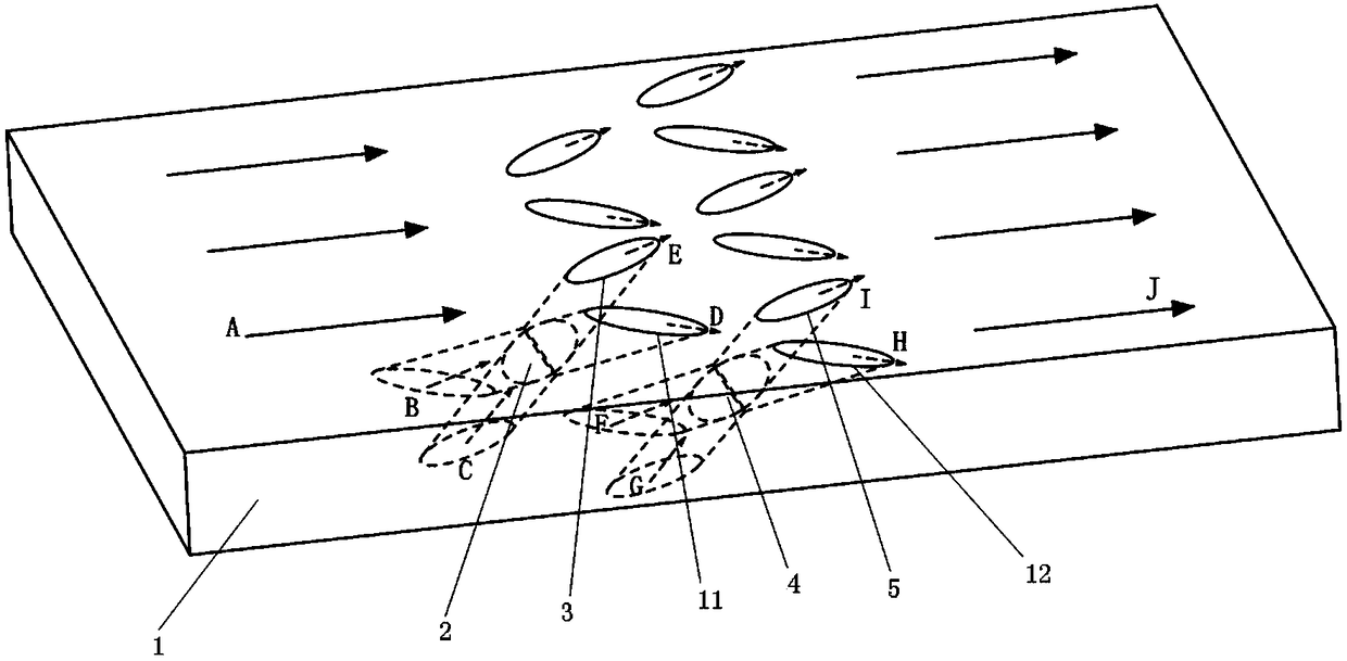
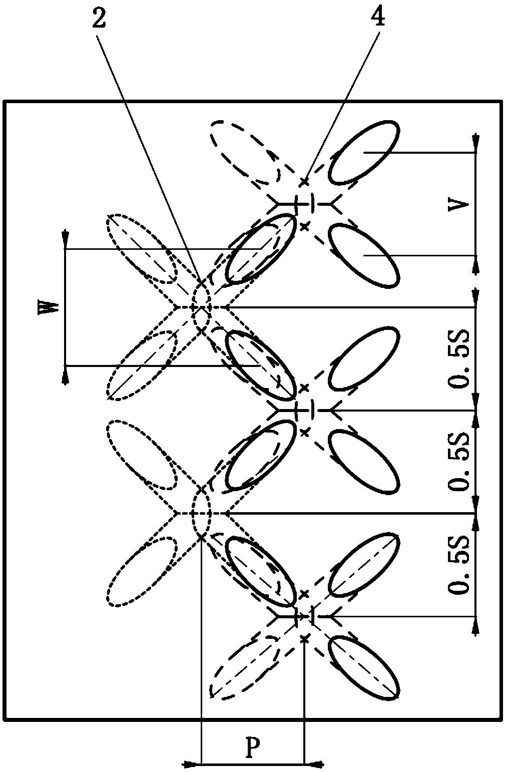
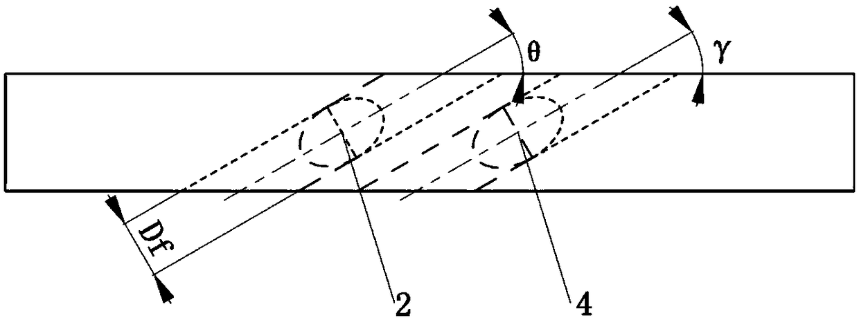
[0031] In this embodiment, the pressure surface cross-type X air film hole 7 and the pressure surface cross-type X air film hole 10 are arranged on the pressure surface of the turbine blade, and the air is supplied by the internal cooling passage 6, and the suction surface cross-type air film hole is arranged on the suction surface of the turbine blade. The X air film hole 9 is supplied by the internal cooling channel 8, wherein the first cylindrical air film hole 3 and the second cylindrical air film hole 11 intersect to form the upstream X air film hole 2, the third cylindrical air film hole 5 and the second cylindrical air film hole The four cylindrical air film holes 12 intersect to form the downstream X air film holes 4, and the upstream X air film holes 2 and the downstream X air film holes 4 are combined to form a cross-shaped X air film hole cooling structure.
[0032] The minimum cross-sectional equivalent diameter D of the first cylindrical air film hole 3, the second...
Embodiment 2
[0035] In this embodiment, the pressure surface cross-type X air film hole 7 and the pressure surface cross-type X air film hole 10 are arranged on the pressure surface of the turbine blade, the air is supplied by the internal cooling passage 6, and the cross-type X air film hole is arranged on the suction surface of the turbine blade. The film hole 9 is supplied by the internal cooling channel 8, wherein the first cylindrical air film hole 3 and the second cylindrical air film hole 11 intersect to form the upstream X air film hole 2, the third cylindrical air film hole 5 and the fourth cylinder The air film holes 12 intersect to form the downstream X air film holes 4, and the upstream X air film holes 2 and the downstream X air film holes 4 are combined to form a cross-shaped X air film hole cooling structure.
[0036] The minimum cross-sectional equivalent diameter D of the first cylindrical air film hole 3, the second cylindrical air film hole 11, the third cylindrical air f...
Embodiment 3
[0039] In this embodiment, the pressure surface cross-type X air film hole 7 and the pressure surface cross-type X air film hole 10 are arranged on the pressure surface of the turbine blade, the air is supplied by the internal cooling passage 6, and the cross-type X air film hole is arranged on the suction surface of the turbine blade. The film hole 9 is supplied by the internal cooling channel 8, wherein the first cylindrical air film hole 3 and the second cylindrical air film hole 11 intersect to form the upstream X air film hole 2; the third cylindrical air film hole 5 and the fourth cylindrical air film hole The air film holes 12 intersect to form the downstream X air film holes 4, and the upstream X air film holes 2 and the downstream X air film holes 4 are combined to form a cross-shaped X air film hole cooling structure.
[0040] The minimum cross-sectional equivalent diameter D of the first cylindrical air film hole 3, the second cylindrical air film hole 11, the third ...
PUM
 Abstract
Description
Claims
Application Information
 - Generate Ideas
- Intellectual Property
- Life Sciences
- Materials
- Tech Scout
- Unparalleled Data Quality
- Higher Quality Content
- 60% Fewer Hallucinations
Browse by: Latest US Patents, China's latest patents, Technical Efficacy Thesaurus, Application Domain, Technology Topic, Popular Technical Reports.
© 2025 PatSnap. All rights reserved.Legal|Privacy policy|Modern Slavery Act Transparency Statement|Sitemap|About US| Contact US: help@patsnap.com