Cross type Y air film hole cooling structure for turbine blade
A technology of turbine blades and air film holes, which is applied to the supporting elements of blades, engine elements, machines/engines, etc., can solve problems such as increasing aerodynamic losses, and achieve the effects of reducing aerodynamic losses, easy processing, and uniform air output.
- Summary
- Abstract
- Description
- Claims
- Application Information
AI Technical Summary
Problems solved by technology
Method used
Image

Examples
Embodiment 1
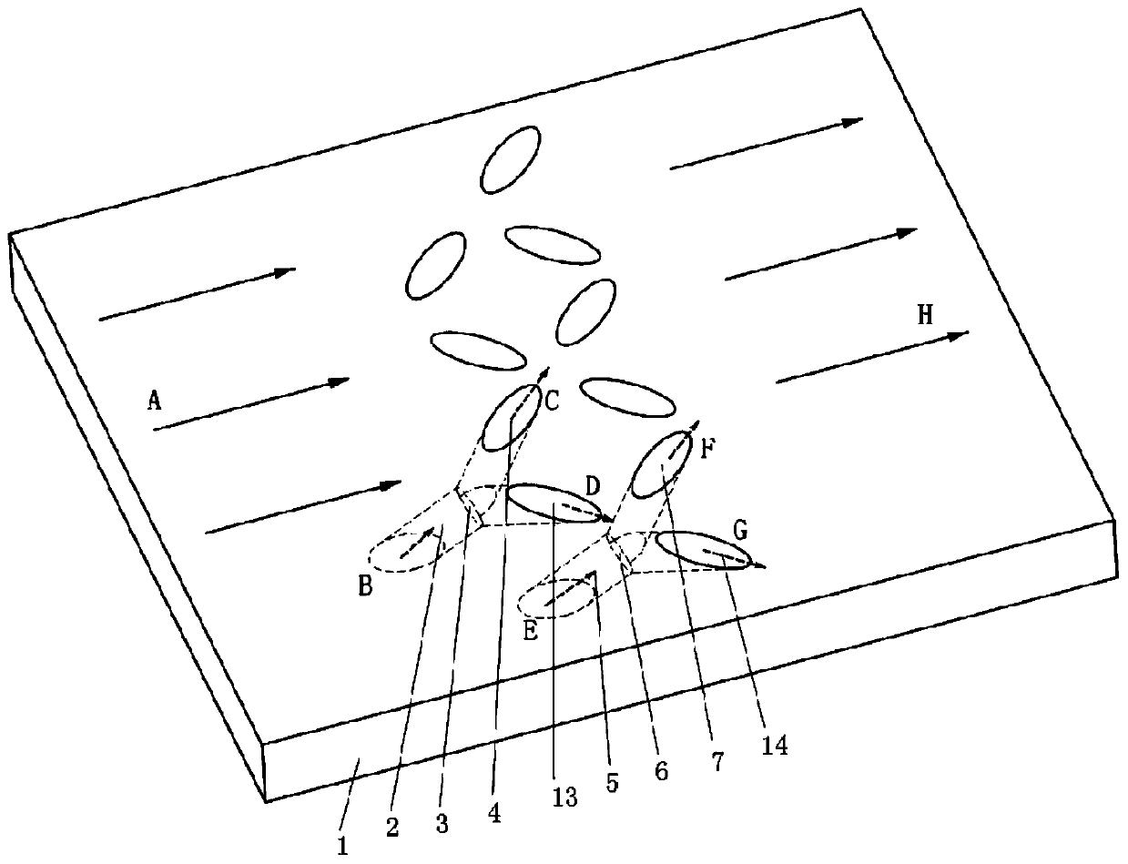
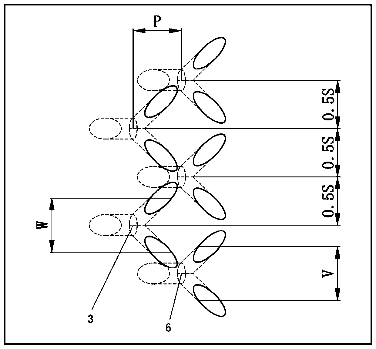
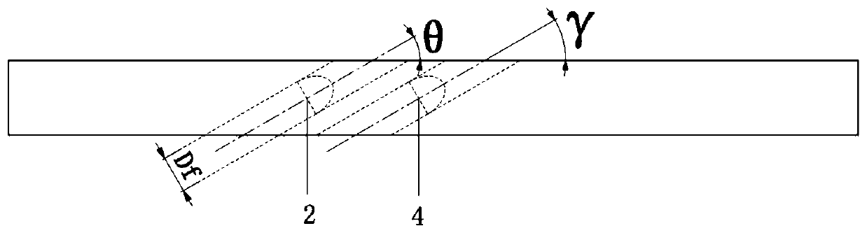
[0027] In this embodiment, the pressure surface cross-shaped Y air film hole 9 and the pressure surface cross-shaped Y air film hole 12 are arranged on the pressure surface of the turbine blade, and the air is supplied by the internal cooling passage 8 and the internal cooling passage 10. The cross-shaped Y air film holes 11 on the suction surface are arranged, and the air is supplied by the inner cooling channel 10 . Among them, the first cylindrical air film hole 4 and the second cylindrical air film hole 13 cross through and stretch their interface to form the upstream Y air film hole 3; the third cylindrical air film hole 7 and the fourth cylindrical air film hole 14 cross through And stretch the junction surface to form the downstream Y air film hole 6, and the upstream Y air film hole 3 and the downstream Y air film hole 6 are combined in cross rows to form a cross-shaped Y air film hole cooling structure.
[0028] In this embodiment, the minimum cross-sectional equivale...
Embodiment 2
[0031] In this embodiment, the cross-shaped Y air film holes 9 and cross-shaped Y air film holes 12 are arranged on the pressure surface of the turbine blade, and the air is supplied by the internal cooling channel 8 and the internal cooling channel 10, and the cross-shaped Y air film hole is arranged on the suction surface of the turbine blade. The air film holes 11 are supplied with air from the internal cooling channel 10 . Among them, the first cylindrical air film hole 4 and the second cylindrical air film hole 13 cross through and stretch their interface to form the upstream Y air film hole 3; the third cylindrical air film hole 7 and the fourth cylindrical air film hole 14 cross through And stretch the junction surface to form the downstream Y air film hole 6; the upstream Y air film hole 3 and the downstream Y air film hole 6 are combined in cross rows to form a cross-shaped Y air film hole cooling structure.
[0032] In this embodiment, the minimum cross-sectional equ...
Embodiment 3
[0035] In this embodiment, the cross-shaped Y air film holes 9 and cross-shaped Y air film holes 12 are arranged on the pressure surface of the turbine blade, and the air is supplied by the internal cooling channel 8 and the internal cooling channel 10, and the cross-shaped Y air film hole is arranged on the suction surface of the turbine blade. The air film hole 11 is supplied by the internal cooling channel 10, wherein the first cylindrical air film hole 4 and the second cylindrical air film hole 13 intersect and penetrate and stretch their interface to form the upstream Y air film hole 3; the third cylindrical air film hole 3 The film hole 7 and the fourth cylindrical air film hole 14 intersect and stretch their interface to form the downstream Y air film hole 6; the upstream Y air film hole 3 and the downstream Y air film hole 6 are combined to form a cross-shaped Y air film hole cooling structure.
[0036] In this embodiment, the minimum cross-sectional equivalent diamete...
PUM
 Abstract
Description
Claims
Application Information
 - Generate Ideas
- Intellectual Property
- Life Sciences
- Materials
- Tech Scout
- Unparalleled Data Quality
- Higher Quality Content
- 60% Fewer Hallucinations
Browse by: Latest US Patents, China's latest patents, Technical Efficacy Thesaurus, Application Domain, Technology Topic, Popular Technical Reports.
© 2025 PatSnap. All rights reserved.Legal|Privacy policy|Modern Slavery Act Transparency Statement|Sitemap|About US| Contact US: help@patsnap.com