
Loader working system based on servo electric cylinders

A servo electric cylinder and working system technology, which is applied to mechanically driven excavators/dredgers, earth movers/shovels, construction, etc., can solve the problem of insufficient precision of electric proportional handle control, large vibration of the whole machine, difficult Real-time control and other issues to achieve the effect of precise and controllable working stroke and working speed, low manufacturing cost and convenient vehicle installation

Pending Publication Date: 2019-03-12
XCMG CONSTR MACHINERY
View PDF7 Cites 3 Cited by
  • Summary
  • Abstract
  • Description
  • Claims
  • Application Information

AI Technical Summary

Problems solved by technology

[0005] The purpose of the present invention is to provide a loader working system based on a servo electric cylinder to solve the technical problems of complex system, low transmission efficiency, large vibration of the whole machine and low control precision brought by the hydraulic drive system of the existing loader. At the same time, it solves the technical problems such as the lack of precision of the existing electric proportional handle control and the difficulty of real-time control.

Method used


Image

  • Loader working system based on servo electric cylinders
  • Loader working system based on servo electric cylinders
  • Loader working system based on servo electric cylinders

Examples


Embodiment 1

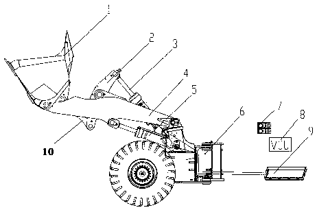
[0024] like figure 1 As shown, a loader working system based on a servo electric cylinder includes a loader body 6, a pair of booms 4 hinged to the loader body 6, and a boom is hinged between the middle of the boom 4 and the loader body 6 Servo electric cylinder 5; through the extension and retraction of the boom servo electric cylinder 5, the lifting and falling of the boom 4 are realized. A bucket 1 is hinged at the other end of a pair of booms 4, and a rocker arm 10 is hinged at the middle of the bucket 1; a rocker tie rod 2 is hinged at the other end of the rocker arm 10; The middle part is hinged on a pair of seat beams, and the bucket servo electric cylinder 3 is hinged between the other end of the rocker arm rod 2 and the loader body 6; Tipping bucket and closing bucket. A battery pack 9 for powering the bucket servo electric cylinder 3 and the boom servo electric cylinder 5 is also installed on the loader body 6 .

Embodiment 2

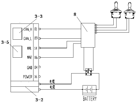
[0026] On the basis of above-mentioned embodiment one, combine again figure 2 and image 3 Shown:

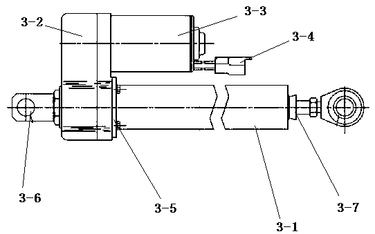
[0027] Boom servo electric cylinder 5 has the same structure as bucket servo electric cylinder 3, taking bucket servo electric cylinder 3 as an example:

[0028] The bucket servo electric cylinder 3 includes a planetary roller screw 3-1, one side of the planetary roller screw 3-1 is fixedly connected with a servo motor 3-2, and the planetary roller screw 3 is driven by the servo motor 3-2 -1, to realize the linear extension and retraction motion of the lead screw in the planetary roller screw 3-1. The servo motor 3-2 is connected to the battery pack 9 through the cable interface 3-6, and the battery pack 9 supplies power for the servo motor 3-2. The servo motor 3-2 is connected with a controller 3-3, the controller 3-3 is connected with a CAN communication interface 3-4, the CAN communication interface 3-4 is connected with the vehicle controller 8CAN bus interface, and the ...


PUM


Abstract

The invention discloses a loader working system based on servo electric cylinders, and belongs to the technical field of shovel-transport engineering machinery vehicles. The movable arm servo electriccylinders are hinged between the middles of movable arms and a loader body. A bucket is hinged to the other ends of a pair of movable arms, and a rocker is hinged to the middle of the bucket. A rocker pull rod is hinged to the other end of the rocker, the middle of the rocker pull rod is hinged to the pair of movable arms, and the bucket servo electric cylinder is hinged between the other end ofthe rocker pull rod and the loader body. A battery pack for supplying power to the bucket servo electric cylinder and the movable arm servo electric cylinders is mounted on the loader body. Drive andcontrol of the servo electric cylinders are achieved by an electronic control handle through CAN bus signal transmission, the system is high in efficiency, and no energy is consumed when the system isnot lifted. The servo electric cylinders have the beneficial effects that the working stroke and the working speed are precise and controllable, high reliability is achieved, no oil leakage is generated, and the system is convenient to mount. The problems that in the original technology, the noise is high, multiple leakage points exist, the transmission efficiency is low, and the maintenance costis high are avoided.

Description

technical field [0001] The invention relates to the technical field of shoveling construction machinery vehicles, in particular to a loader working system based on a servo electric cylinder. Background technique [0002] Loaders are used for loading, unloading, pushing, construction and other operations of bulk materials such as soil, gravel, coal, etc., and are widely used in various construction sites. The working system of the current loader is mainly composed of hydraulic pumps, hydraulic valve groups, hydraulic oil and related pipelines. Through the mutual conversion of mechanical energy and hydraulic energy, the hydraulic cylinder is driven to perform telescopic movements to meet the lifting and lowering of the boom. flip. [0003] However, the hydraulic pipeline connection of the existing hydraulic system is complex and prone to oil leakage and system installation is inconvenient; at the same time, the hydraulic transmission efficiency is low, resulting in waste of e...

Claims


Application Information

Patent Timeline
Patent Type & Authority Applications(China)
IPC IPC(8): E02F3/28E02F3/42E02F3/43
CPCE02F3/28E02F3/425E02F3/43
Inventor 李松李寒光董雯雯侯璐王苏东侯卓磊李夏宇王伟陈立仁邱楚然江云鹤黄二静耿睿
Owner XCMG CONSTR MACHINERY
Learn More