Liquid crystal display structure

A liquid crystal display, one-to-one corresponding technology, applied in instruments, nonlinear optics, optics, etc., can solve the problems of in-cell polarizer manufacturing difficulties, commercialization difficulties, non-mixing, etc., to save power consumption and reduce light energy. , the effect of improving the efficiency of use

Pending Publication Date: 2019-03-08
TOMI CHENGDU APPLIED TECH RES INST CO LTD
View PDF0 Cites 4 Cited by
  • Summary
  • Abstract
  • Description
  • Claims
  • Application Information

AI Technical Summary

Problems solved by technology

However, in-cell polarizers are not only technically difficult to manufacture, but also very expensive, making commercialization very difficult
The light of QD is emitted in all directions, and the light to the bottom can be emitted to the upper part through the reflective diaphragm, but how to make the RGB color light emitted from the QD to the upper part not mixed, this is not realized by the existing technology

Method used


Image

  • Liquid crystal display structure

Examples


Embodiment Construction

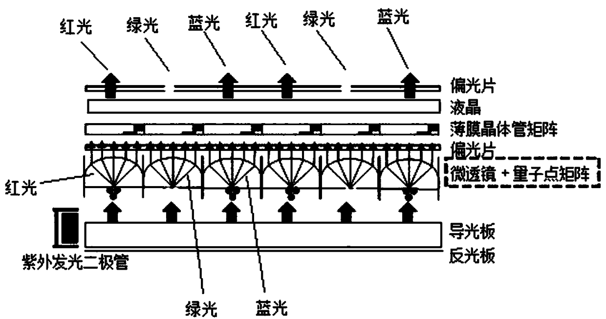
[0018] The present invention will be further described below in conjunction with the accompanying drawings.

[0019] Such as figure 1 As shown, a liquid crystal display structure includes a backlight module block (including sequentially laminated reflectors and light guide plates), a lower polarizer, a thin film transistor matrix, liquid crystal, an upper polarizer, and also includes an ultraviolet light source, a quantum dot matrix layer and The microlens array layer, the ultraviolet light source is located on the side of the backlight module, the backlight module, the quantum dot matrix layer, the microlens array layer, the lower polarizer, the thin film transistor matrix, the liquid crystal and the upper polarizer are stacked in sequence, and the The microlens has corresponding quantum dots in the direction perpendicular to the lamination. The size of the quantum dots should meet the conditions for forming RGB colors. The refraction part of the microlens makes the refracted...


PUM


Abstract

The invention relates to the field of liquid crystal display and discloses a liquid crystal display structure which comprises a backlight module, a lower-layer polaroid, a thin film transistor matrix,a liquid crystal and an upper-layer polaroid and further comprises an ultraviolet source, a quantum dot matrix layer and a microlens array layer. The ultraviolet source is positioned on the side faceof the backlight module, the backlight module, the quantum dot matrix layer, the microlens array layer, the lower-layer polaroid, the thin film transistor matrix, the liquid crystal and the upper-layer polaroid are sequentially arranged in a laminated manner, a microlens has corresponding quantum dot matters in a direction perpendicular to lamination, a refractive portion of the microlens enablesrefracted RGB color light to be perpendicular to the lamination direction. A quantum dot matrix layer is arranged at the bottom, RGB color is emitted by controlling quantum dot size, the microlens isadopted for one-way emission of the RGB color, color filters in conventional methods are omitted, and light using efficiency is improved; on the premise of same power consumption, screen using duration or brightness of the display screen is improved.

Description

technical field [0001] The invention relates to the technical field of liquid crystal display, in particular to a liquid crystal display structure. Background technique [0002] Liquid crystal display (LCD for short) is the most representative display used by the public today. A liquid crystal display is usually composed of a backlight unit (BLU for short) and a liquid crystal (LC for short), and the light emitted from the backlight module is driven by the liquid crystal to adjust the switch in each pixel. At this time, the manipulated light is filtered through a color filter (C / F for short) located above the liquid crystal, thereby realizing RGB colors. Different from organic light-emitting diodes (OLEDs) that emit light by themselves, LCDs cannot emit light by themselves. The reason why we can see the picture on the display is through the light emitted from the BLU. Therefore, the BLU making the light source in the LCD display and the light made using the BLU constitute...

Claims


Application Information

Patent Timeline
Patent Type & Authority Applications(China)
IPC IPC(8): G02F1/13357G02F1/1335
CPCG02F1/133615G02F1/133526G02F1/133617
Inventor 李珪
Owner TOMI CHENGDU APPLIED TECH RES INST CO LTD
Why Eureka
Try Eureka