
A Quantitative Measurement System and Method for Refractive Index Field Based on Phase Calibration

A quantitative measurement and refractive index technology, which is applied in the phase influence characteristic measurement, measurement device, instrument, etc., can solve the problems of large influence on the result, insufficient contrast, and little quantitative analysis, etc., and achieve the effect of quantitative measurement and reduction of measurement error

Active Publication Date: 2020-04-07
SUN YAT SEN UNIV
View PDF9 Cites 0 Cited by
  • Summary
  • Abstract
  • Description
  • Claims
  • Application Information

AI Technical Summary

Problems solved by technology

Both of the above two methods have strict requirements on the light source, but for black and white schlieren, there are less restrictions on the light source, but due to insufficient contrast and the influence of optical path errors on the results, they are rarely used in quantitative analysis

Method used


Image

  • A Quantitative Measurement System and Method for Refractive Index Field Based on Phase Calibration
  • A Quantitative Measurement System and Method for Refractive Index Field Based on Phase Calibration
  • A Quantitative Measurement System and Method for Refractive Index Field Based on Phase Calibration

Examples


Embodiment

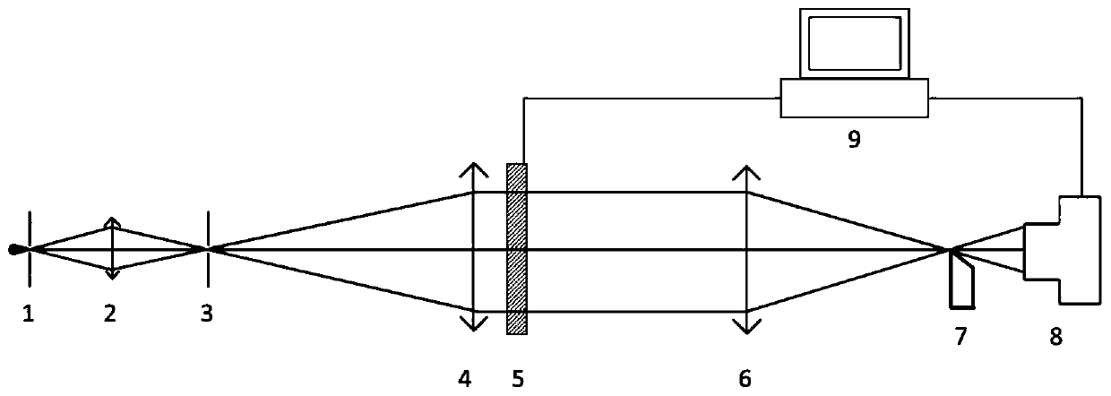
[0046] This embodiment provides a quantitative measurement system for the refractive index field based on phase calibration, such as figure 1 As shown, it includes a light source 1 and a focus lens 2, an aperture diaphragm 3, a collimator lens 4, a detection area 5, an imaging lens 6, a knife edge 7, and a detector 8 arranged sequentially behind the light source 1, and the detection area 5 is used for calibration. It is used to place the standard phase control element. During the measurement, the standard phase control element is replaced by the field to be measured and placed in the detection area 5; the light emitted by the light source 1 is converged at the pinhole diaphragm 3 through the focusing lens 2, and then passed through the collimating lens 4 becomes parallel light, and after passing through the detection area 5, the light emitted by the imaging lens 6 is cut by the knife edge 7 and then imaged on the detection surface of the detector 8; it also includes a control u...


PUM


Abstract

The invention relates to a phase calibration based quantitative measurement system and method for a refractive index field. The system comprises a light source as well as a focusing lens, a microporediaphragm, a collimating lens, a detection area, an imaging lens, a knife edge and a detector which are arranged sequentially behind the light source, wherein during calibrating, the detection area isused for accommodating a standard phase control element, and during measuring, the standard phase control element is replaced with a to-be-detected field to be put in the detection area; the system further comprises a control unit used for controlling the detector and the standard phase control element; during calibrating, the control unit controls the standard phase control element to produce refractive index gradient with different strengths in different positions and controls the detector to execute recording, and therefore, a response relation of different sizes of bending angles in different positions of the system on the detector is acquired; during measuring, the detector is controlled to detect the to-be-detected field, and refractive index distribution of the to-be-detected fieldis acquired according to the response relation. According to the system and the method, measurement errors can be reduced, and accurate and quantitative measurement for the refractive index field canbe realized.

Description

technical field [0001] The invention relates to the technical field of schlieren optical imaging for detecting the distribution of the refractive index field of a fluid, and more particularly relates to a system and method for quantitatively measuring the refractive index field based on phase calibration. Background technique [0002] Schlieren technology was first proposed and used by German physicist August Toepler. After continuous improvement and development, various schlieren imaging technologies such as black and white schlieren, color schlieren, and interference schlieren have been developed. Schlieren technology can be used to observe the refractive index distribution of the field to be measured, and obtain the distribution field information of the corresponding physical quantities from the relationship between the fluid refractive index and other properties such as density, pressure, temperature, and chemical composition. It has a wide range of applications in exper...

Claims


Application Information

Patent Timeline
Patent Type & Authority Patents(China)
IPC IPC(8): G01N21/41G01N21/01
CPCG01N21/01G01N21/4133
Inventor 王嘉辉汤国靖欧阳昕杨萍罗万嵩
Owner SUN YAT SEN UNIV
Learn More