Vibration signal conditioning and data converter
A technology of data converters and vibration signals, applied in analog/digital conversion, code conversion, physical parameter compensation/prevention, etc., can solve problems such as prevention before they happen, to ensure safe operation, fast and accurate accident hidden dangers, and reduce failure rate Effect
- Summary
- Abstract
- Description
- Claims
- Application Information
AI Technical Summary
Problems solved by technology
Method used
Image
Examples
Embodiment 1
[0025] Such as figure 1 As shown, the present embodiment provides a vibration signal conditioning and data converter, including a piezoelectric acceleration sensor 1 with an IEPE built-in charge amplifier, a vibration detection circuit module 2 and a digital circuit module 3, and the vibration detection circuit module 2 includes sequentially connected Constant current source circuit 4, input amplifier 5, program-controlled amplifier 6, output amplifier 7, integrator 8, analog switch 9, anti-aliasing filter 10 and ADC analog-to-digital converter 11, and the digital circuit module 3 is connected through a 3-bit control line Next to the program-controlled amplifier 6, the digital circuit module 3 is connected to the analog switch 9 through a 2-bit control line, the digital circuit module 3 is connected to the anti-aliasing filter 10, and the cut-off frequency control for the anti-aliasing filter 10 is realized through the PWM signal, and the digital The circuit module 3 is connec...
Embodiment 2
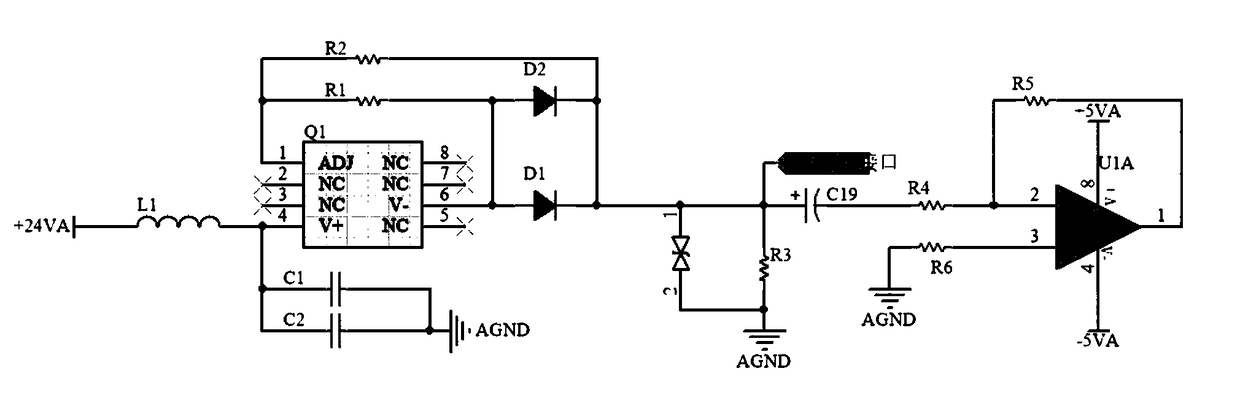
[0037] The constant current source circuit 4 is used to provide a constant drive current for the piezoelectric acceleration sensor 1, because the constant drive current is easily affected by the temperature coefficient, and a static DC bias voltage will be generated on the signal line of the piezoelectric acceleration sensor 1, because This voltage is not an effective vibration signal, so it will affect the measurement accuracy of the vibration signal of the piezoelectric acceleration sensor 1 .
[0038] In order to ensure the stability of the constant driving current and the measurement accuracy of the piezoelectric acceleration sensor 1, as figure 2 As shown, the constant current source circuit 4 includes two parts: a temperature compensation circuit and a bias isolation circuit.
[0039] The temperature compensation circuit includes a resistor R1, a resistor R2, a diode D1, a diode D2 and a constant current source chip Q1. The constant current source chip Q1 is provided wi...
PUM
 Abstract
Description
Claims
Application Information
 - Generate Ideas
- Intellectual Property
- Life Sciences
- Materials
- Tech Scout
- Unparalleled Data Quality
- Higher Quality Content
- 60% Fewer Hallucinations
Browse by: Latest US Patents, China's latest patents, Technical Efficacy Thesaurus, Application Domain, Technology Topic, Popular Technical Reports.
© 2025 PatSnap. All rights reserved.Legal|Privacy policy|Modern Slavery Act Transparency Statement|Sitemap|About US| Contact US: help@patsnap.com


