Power station waste heat recycling device and energy saving system

A heat recovery device and heat recovery technology, applied in the direction of steam recovery, steam engine device, machine/engine, etc., can solve the problems of high parameters of power station equipment, neglect of heat recovery, and small energy recovery, so as to improve the safety and economic level, Ease of retrofitting and energy saving effects

Pending Publication Date: 2019-03-08
郑州赛为机电设备有限公司
View PDF12 Cites 1 Cited by
  • Summary
  • Abstract
  • Description
  • Claims
  • Application Information

AI Technical Summary

Problems solved by technology

This kind of waste heat recovery device generally adopts a single tube or hybrid heat exchanger structure, and the heated medium is recovered through the pump station. This kind of device has a simple structure, a single function, and a small amount of energy-saving recovery.
However, the equipment parameters of the power station are high, the system piping is complex, involving multiple equipment and multiple interdisciplinary specialties, and the design usually focuses on the safety of the drainage system and the recovery of softened water, while ignoring the recovery of this part of the heat. With the increase of unit capacity and parameters, the heat loss of this part is also very significant

Method used


Image

  • Power station waste heat recycling device and energy saving system
  • Power station waste heat recycling device and energy saving system
  • Power station waste heat recycling device and energy saving system

Examples


Embodiment Construction

[0031] The technical solutions of the present invention will be described in further detail below through specific implementation methods.

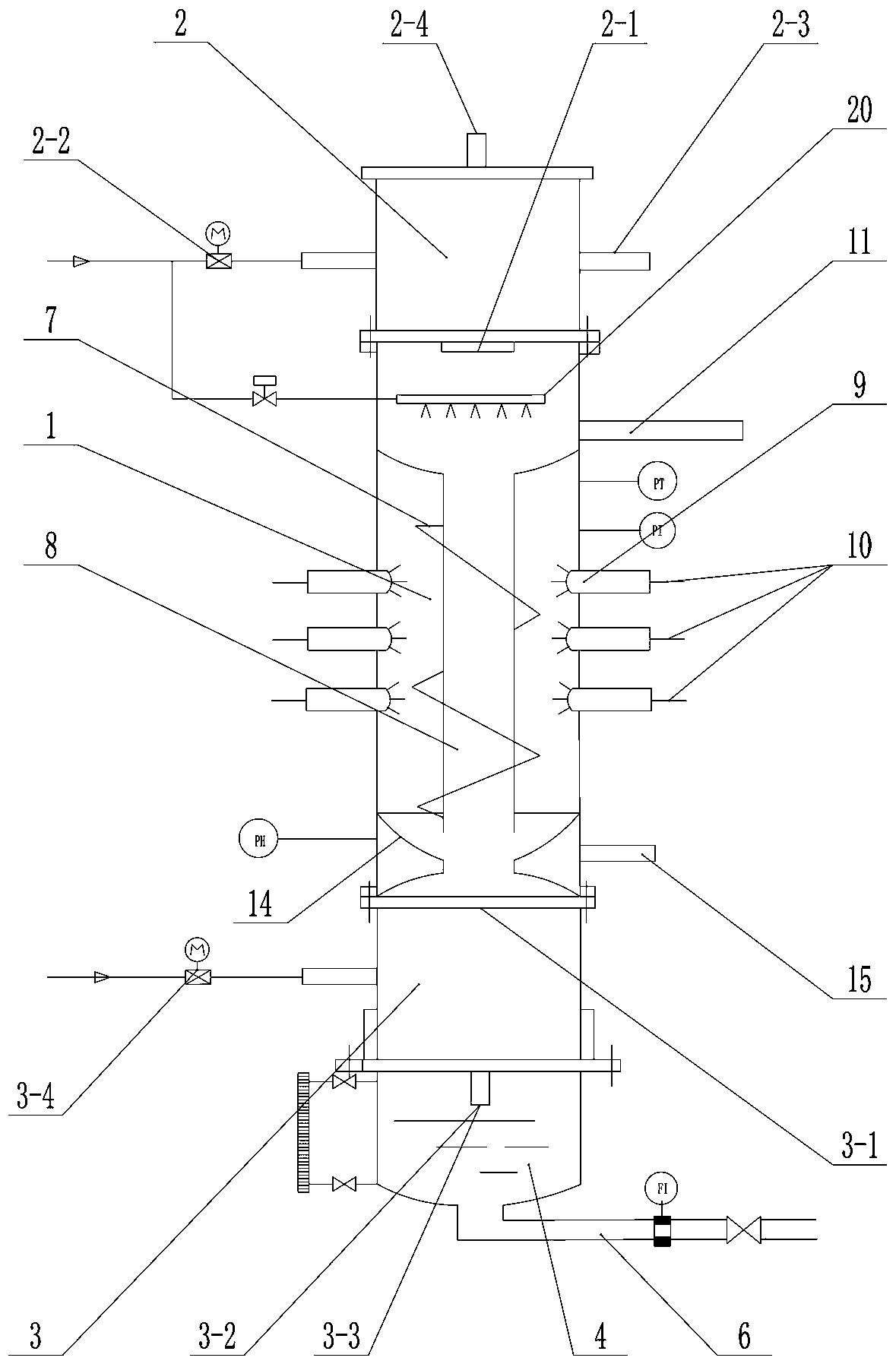
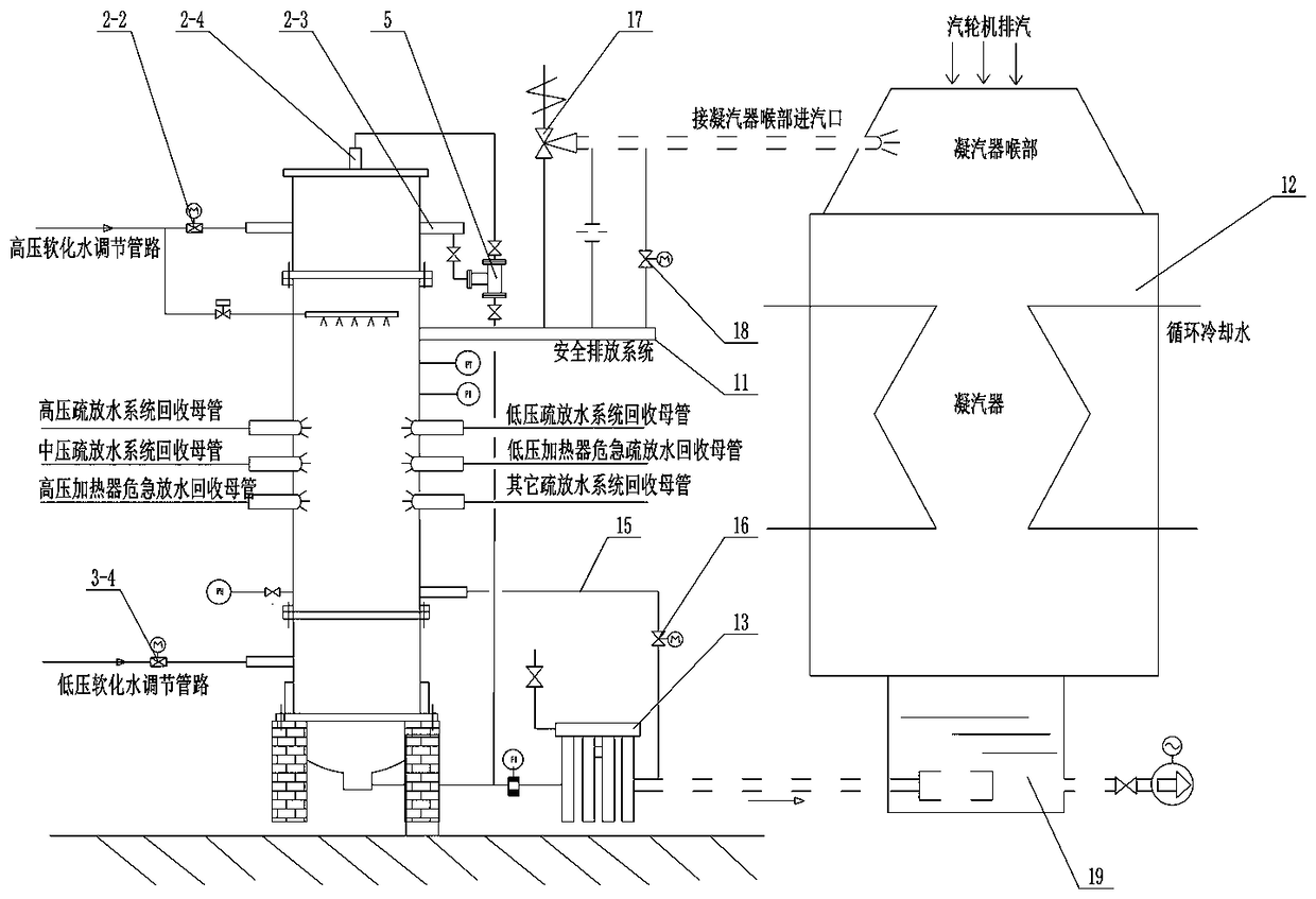
[0032] Such as figure 1 and figure 2 As shown, a waste heat recovery device for a power station includes a steam-water separator 1, a high-pressure waste heat recovery device 2, a low-pressure waste heat recovery device 3, a waste heat recovery water tank 4, a gas-liquid two-phase steam trap 5, and a waste heat recovery mother Pipe 6, the high-pressure waste heat recovery device 2, the steam-water separator 1 and the low-pressure waste heat recovery device 3 are connected sequentially from top to bottom;

[0033] The steam-water separator 1 is equipped with a spiral separator 7, a waste heat connecting pipe 8 and a plurality of steam mufflers 9, and a plurality of steam mufflers 9 are used to connect the main pipe 10 of the water drainage system, such as the recovery main pipe of the high-pressure water drainage system , the main pipe ...


PUM


Abstract

The invention provides a power station waste heat recycling device and an energy saving system. A steam and water separator, a high voltage waste heat recycling unit, a low voltage waste heat recycling unit, a waste heat recycling water tank, a gas-liquid two phase steam trap and a waste heat recycling mother pipe are included; a steam inlet of the high voltage waste heat recycling unit communicates with the steam and water separator and corresponds to the upper end of a waste heat communicating pipe; a steam condensate water outlet of the high voltage waste heat recycling unit is connected tothe gas-liquid two phase steam trap, and then is combined with a high pressure softened water outlet of the high voltage waste heat recycling unit and connected to the waste heat recycling water tank; a steam inlet of the low voltage waste heat recycling unit communicates with the steam and water separator and corresponds to the lower end of the waste heat communicating pipe; a low pressure softened water outlet of the low voltage waste heat recycling unit is combined with the steam condensate water outlet and connected to the waste heat recycling water tank; and a water outlet of the waste heat recycling water tank is connected with the waste heat recycling mother pipe. The power station waste heat recycling device and the energy saving system have the advantages of being scientific in design, full in waste heat recycling, safe and stable, convenient to transform, and good in energy-saving effect.

Description

technical field [0001] The invention relates to a device for recovering waste heat of a power station, in particular to a device for recovering waste heat of a power station and an energy-saving system. Background technique [0002] Whether it is a coal-fired or gas-fired thermal power station, or a nuclear power station that uses atomic energy, its thermal equipment and thermal piping systems are equipped with drainage pipe valve systems. The water is drained through the drain water system, and most of the drain water is steam or steam-water mixture containing heat. After expansion, it is directly discharged into the condenser. In addition to recovering softened water, a large amount of heat is taken away by the circulating cooling water, that is waste of heat. In addition, during the normal operation of the unit, the water drain valves of the thermal system are frequently switched on and off and washed by steam. Generally, some valves will leak internally for a long time....

Claims


Application Information

Patent Timeline
Patent Type & Authority Applications(China)
IPC IPC(8): F01K19/00F01K13/02F01K9/00
CPCF01K9/00F01K13/02F01K19/00
Inventor 姚杰新姬鄂豫
Owner 郑州赛为机电设备有限公司
Why Eureka
Try Eureka